Toyota CH-R Service Manual: Parts Location
PARTS LOCATION
ILLUSTRATION
|
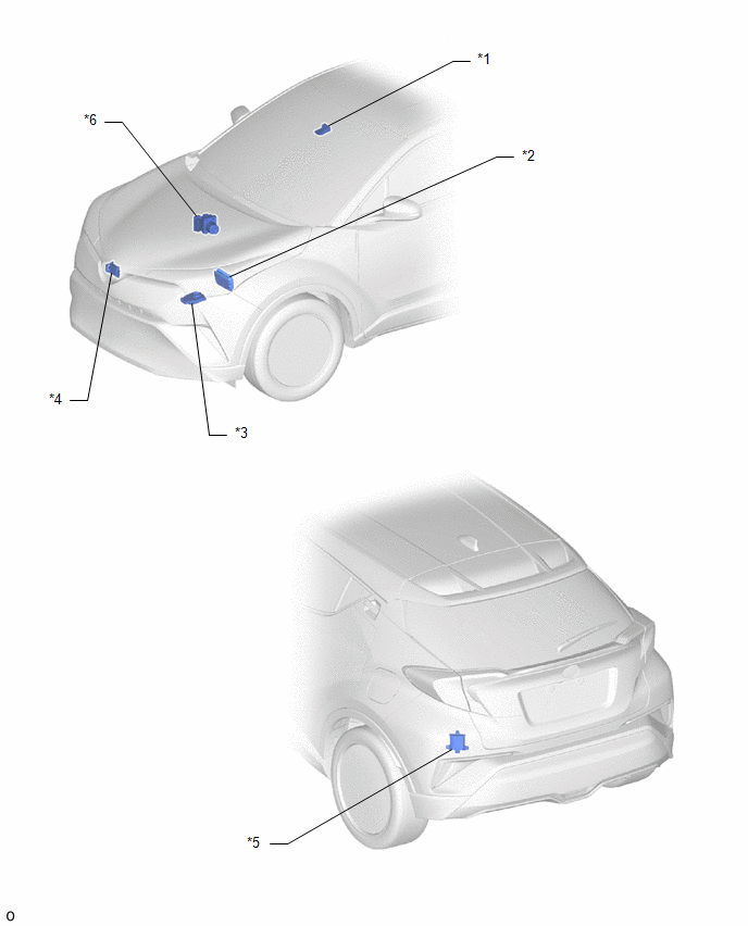
*1 |
FORWARD RECOGNITION CAMERA (w/ Toyota Safety Sense P) |
*2 |
ECM |
|
*3 |
HEADLIGHT ECU SUB-ASSEMBLY LH (for LED Headlight) |
*4 |
MILLIMETER WAVE RADAR SENSOR ASSEMBLY (w/ Toyota Safety Sense P) |
|
*5 |
BLIND SPOT MONITOR SENSOR LH (w/ Blind Spot Monitor System) |
*6 |
BRAKE ACTUATOR ASSEMBLY |
ILLUSTRATION
|
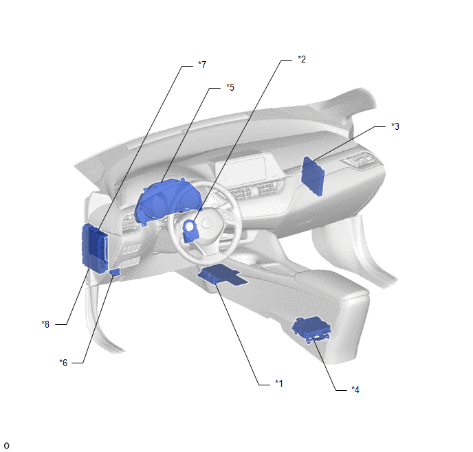
*1 |
AIRBAG SENSOR ASSEMBLY |
*2 |
STEERING SENSOR |
|
*3 |
CERTIFICATION ECU (SMART KEY ECU ASSEMBLY) (w/ Smart Key System) |
*4 |
DCM (TELEMATICS TRANSCEIVER) (w/ Telematics Transceiver) |
|
*5 |
COMBINATION METER ASSEMBLY |
*6 |
DLC3 |
|
*7 |
MAIN BODY ECU (MULTIPLEX NETWORK BODY ECU) |
*8 |
INSTRUMENT PANEL JUNCTION BLOCK ASSEMBLY |
ILLUSTRATION
|
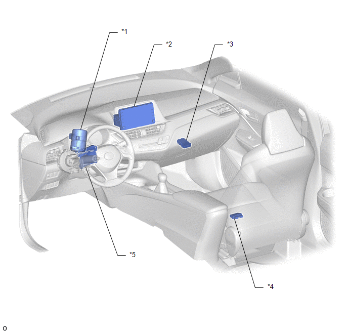
*1 |
POWER STEERING ECU ASSEMBLY |
*2 |
RADIO AND DISPLAY RECEIVER ASSEMBLY (for Radio and Display Type) |
|
*3 |
CENTRAL GATEWAY ECU (NETWORK GATEWAY ECU) |
*4 |
OCCUPANT DETECTION ECU (w/ Occupant Detection ECU) |
|
*5 |
AIR CONDITIONING AMPLIFIER ASSEMBLY |
- |
- |
ILLUSTRATION
|
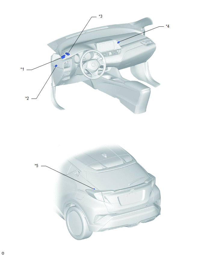
*1 |
NO. 1 CAN JUNCTION CONNECTOR |
*2 |
NO. 3 CAN JUNCTION CONNECTOR |
|
*3 |
NO. 4 CAN JUNCTION CONNECTOR |
*4 |
NO. 5 CAN JUNCTION CONNECTOR |
|
*5 |
NO. 6 CAN JUNCTION CONNECTOR (w/ Blind Spot Monitor System) |
- |
- |
 Precaution
PRECAUTION
IGNITION SWITCH EXPRESSIONS
(a) The type of ignition switch used on this model differs according to the specifications
of the vehicle. The expressions listed in the table below are used ...
 System Diagram
SYSTEM DIAGRAM
(a) The CAN communication system is composed of 5 buses.
*A
w/ Blind Spot Monitor System
-
-
CAN Main Bus Line
...
Other materials:
Toyota CH-R Service Manual > Seat Belt Warning System(w/o Occupant Classification System): Problem Symptoms Table
PROBLEM SYMPTOMS TABLE
HINT:
Use the table below to help determine the cause of problem symptoms.
If multiple suspected areas are listed, the potential causes of the symptoms
are listed in order of probability in the "Suspected Area" column of the
table. Check each sy ...
Toyota CH-R Service Manual > Integration Relay: Components
COMPONENTS
ILLUSTRATION
*1
NO. 1 INTEGRATION RELAY
*2
NO. 1 RELAY BLOCK COVER
...
Toyota C-HR (AX20) 2023-2026 Owner's Manual
Toyota CH-R Owners Manual
- For safety and security
- Instrument cluster
- Operation of each component
- Driving
- Interior features
- Maintenance and care
- When trouble arises
- Vehicle specifications
- For owners
Toyota CH-R Service Manual
- Introduction
- Maintenance
- Audio / Video
- Cellular Communication
- Navigation / Multi Info Display
- Park Assist / Monitoring
- Brake (front)
- Brake (rear)
- Brake Control / Dynamic Control Systems
- Brake System (other)
- Parking Brake
- Axle And Differential
- Drive Shaft / Propeller Shaft
- K114 Cvt
- 3zr-fae Battery / Charging
- Networking
- Power Distribution
- Power Assist Systems
- Steering Column
- Steering Gear / Linkage
- Alignment / Handling Diagnosis
- Front Suspension
- Rear Suspension
- Tire / Wheel
- Tire Pressure Monitoring
- Door / Hatch
- Exterior Panels / Trim
- Horn
- Lighting (ext)
- Mirror (ext)
- Window / Glass
- Wiper / Washer
- Door Lock
- Heating / Air Conditioning
- Interior Panels / Trim
- Lighting (int)
- Meter / Gauge / Display
- Mirror (int)
- Power Outlets (int)
- Pre-collision
- Seat
- Seat Belt
- Supplemental Restraint Systems
- Theft Deterrent / Keyless Entry

0.0105