Toyota CH-R Service Manual: System Diagram
SYSTEM DIAGRAM
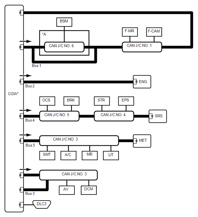
(a) The CAN communication system is composed of 5 buses.
|
*A |
w/ Blind Spot Monitor System |
- |
- |
 |
CAN Main Bus Line |
 |
Terminating Resistor |
 |
CAN Branch Line |
* |
Gateway Function Equipped ECU |
.png) |
Bus Monitoring Direction |
- |
- |
|
Connected to |
Code |
ECU/Sensor Name |
CAN DTC Storage |
Note |
|---|---|---|---|---|
|
- |
CGW |
Central Gateway ECU (Network Gateway ECU) |
- |
- |
|
- |
DLC3 |
DLC3 |
- |
- |
|
Bus 1 |
BSM |
Blind Spot Monitor Sensor LH |
Available |
w/ Blind Spot Monitor System |
|
F-CAM |
Forward Recognition Camera |
Available |
w/ Toyota Safety Sense P |
|
|
F-MR |
Millimeter Wave Radar Sensor Assembly |
Available |
w/ Toyota Safety Sense P |
|
|
CAN J/C NO. 6 |
No. 6 CAN Junction Connector |
- |
w/ Blind Spot Monitor System |
|
|
CAN J/C NO. 1 |
No. 1 CAN Junction Connector |
- |
- |
|
|
Bus 2 |
ENG |
ECM |
Available |
- |
|
Bus 3 |
AV |
Radio and Display Receiver Assembly |
Available |
for Radio and Display Type |
|
DCM |
DCM (Telematics Transceiver) |
Available |
w/ Telematics Transceiver |
|
|
CAN J/C NO. 3 |
No. 3 Junction Connector |
- |
- |
|
|
Bus 4 |
STR |
Steering Sensor |
- |
- |
|
EPS |
Power Steering ECU Assembly |
Available |
- |
|
|
BRK |
Brake Actuator Assembly |
Available |
- |
|
|
OCS |
Occupant Detection ECU |
Available |
w/ Occupant Detection ECU |
|
|
SRS |
Airbag Sensor Assembly |
Available |
- |
|
|
CAN J/C NO. 5 |
No. 5 CAN Junction Connector |
- |
- |
|
|
CAN J/C NO. 4 |
No. 4 CAN Junction Connector |
- |
- |
|
|
Bus 5 |
A/C |
Air Conditioning Amplifier Assembly |
Available |
Connected to LIN communication system |
|
SMT |
Certification ECU (Smart Key ECU Assembly) |
Available |
w/ Smart Key System |
|
|
MB |
Main Body ECU (Multiplex Network Body ECU) |
Available |
Connected to LIN communication system |
|
|
LIT |
Headlight ECU Sub-assembly LH |
Available |
for LED Headlight |
|
|
MET |
Combination Meter Assembly |
Available |
- |
|
|
CAN J/C NO. 3 |
No. 3 CAN Junction Connector |
- |
- |
 Parts Location
PARTS LOCATION
ILLUSTRATION
*1
FORWARD RECOGNITION CAMERA
(w/ Toyota Safety Sense P)
*2
ECM
*3
HEADLIGHT ECU SUB-ASSEMBLY ...
 System Description
SYSTEM DESCRIPTION
BRIEF DESCRIPTION
(a) The Controller Area Network (CAN) is a serial data communication system for
real time application. It is a vehicle multiplex communication system which has ...
Other materials:
Toyota CH-R Service Manual > Air Conditioning Unit(for Valeo Made): Installation
INSTALLATION
PROCEDURE
1. INSTALL LOWER DEFROSTER NOZZLE ASSEMBLY
(a) Engage the claws to install the lower defroster nozzle assembly.
2. TEMPORARILY INSTALL AIR CONDITIONER UNIT ASSEMBLY
(a) Temporarily install the air conditioner unit ...
Toyota CH-R Service Manual > Airbag System: Pressure Sensor Difference for Front Door (B166A/72)
DESCRIPTION
The door side airbag sensor LH and door side airbag sensor RH detect impacts
to the vehicle through changes in pressure inside the front doors caused by deformation
of the outer side of the front doors and send signals to the airbag sensor assembly.
Based on the signals sent by the ...
Toyota C-HR (AX20) 2023-2026 Owner's Manual
Toyota CH-R Owners Manual
- For safety and security
- Instrument cluster
- Operation of each component
- Driving
- Interior features
- Maintenance and care
- When trouble arises
- Vehicle specifications
- For owners
Toyota CH-R Service Manual
- Introduction
- Maintenance
- Audio / Video
- Cellular Communication
- Navigation / Multi Info Display
- Park Assist / Monitoring
- Brake (front)
- Brake (rear)
- Brake Control / Dynamic Control Systems
- Brake System (other)
- Parking Brake
- Axle And Differential
- Drive Shaft / Propeller Shaft
- K114 Cvt
- 3zr-fae Battery / Charging
- Networking
- Power Distribution
- Power Assist Systems
- Steering Column
- Steering Gear / Linkage
- Alignment / Handling Diagnosis
- Front Suspension
- Rear Suspension
- Tire / Wheel
- Tire Pressure Monitoring
- Door / Hatch
- Exterior Panels / Trim
- Horn
- Lighting (ext)
- Mirror (ext)
- Window / Glass
- Wiper / Washer
- Door Lock
- Heating / Air Conditioning
- Interior Panels / Trim
- Lighting (int)
- Meter / Gauge / Display
- Mirror (int)
- Power Outlets (int)
- Pre-collision
- Seat
- Seat Belt
- Supplemental Restraint Systems
- Theft Deterrent / Keyless Entry

0.0193