Toyota CH-R Service Manual: Installation
INSTALLATION
PROCEDURE
1. INSTALL HOLE PLUG
(a) Install the 4 hole plugs to the front suspension crossmember sub-assembly.
HINT:
There are 2 different shapes of hole plug.
2. INSTALL FRONT SUSPENSION MEMBER PLATE
(a) Install the 2 front suspension member plates to the front suspension crossmember sub-assembly.
3. INSTALL ENGINE MOVING CONTROL ROD
(a) Install the engine moving control rod to the front suspension crossmember sub-assembly with the bolt.
Torque:
200 N·m {2039 kgf·cm, 148 ft·lbf}
4. TEMPORARILY INSTALL FRONT LOWER NO. 1 SUSPENSION ARM SUB-ASSEMBLY LH
(a) Temporarily install the front lower No. 1 suspension arm sub-assembly LH to the front suspension crossmember sub-assembly with the 2 bolts and nut.
5. TEMPORARILY INSTALL FRONT LOWER NO. 1 SUSPENSION ARM SUB-ASSEMBLY RH
HINT:
Perform the same procedure as for the LH side.
6. INSTALL FRONT STABILIZER BAR
Click here
.gif)
7. INSTALL FRONT NO. 1 STABILIZER BRACKET LH
Click here
8. INSTALL FRONT NO. 1 STABILIZER BRACKET RH
HINT:
Perform the same procedure as for the LH side.
9. INSTALL STEERING LINK ASSEMBLY
(a) Install the steering link assembly to the front suspension crossmember sub-assembly with the 2 bolts and 2 new nuts.
Torque:
133 N·m {1356 kgf·cm, 98 ft·lbf}
NOTICE:
- Because the nut has its own stopper, do not turn the nut. Tighten the bolt with the nut secured.
- Make sure to tighten the bolts starting from the left side of the vehicle.
10. INSTALL FRONT SUSPENSION CROSSMEMBER SUB-ASSEMBLY
(a) Slowly jack up the front suspension crossmember sub-assembly with an engine lifter using 4 attachments or equivalent tools.
CAUTION:
- The front suspension crossmember sub-assembly is a very heavy component. Make sure that it is supported securely.
- If the front suspension crossmember sub-assembly is not securely supported, it may drop, resulting in serious injury.
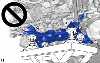
NOTICE:
Use attachments to keep the front suspension crossmember sub-assembly level.
(b) Install the front suspension crossmember sub-assembly to the vehicle body with the 6 bolts.
Torque:
141 N·m {1438 kgf·cm, 104 ft·lbf}
(c) Lower the engine lifter.
(d) Install the engine moving control rod with the bolt.
Torque:
170 N·m {1734 kgf·cm, 125 ft·lbf}
(e) Install the 2 wire harness clamp brackets to the front suspension crossmember sub-assembly with the 2 bolts.
Torque:
13 N·m {133 kgf·cm, 10 ft·lbf}
11. INSTALL FRONT LOWER NO. 1 SUSPENSION ARM SUB-ASSEMBLY LH
(a) Install the front lower No. 1 suspension arm sub-assembly LH to the front lower ball joint assembly LH with the bolt and 2 nuts.
Torque:
89 N·m {908 kgf·cm, 66 ft·lbf}
12. CONNECT FRONT LOWER NO. 1 SUSPENSION ARM SUB-ASSEMBLY RH
HINT:
Perform the same procedure as for the LH side.
13. CONNECT TIE ROD END SUB-ASSEMBLY LH
Click here
14. CONNECT TIE ROD END SUB-ASSEMBLY RH
HINT:
Perform the same procedure as for the LH side.
15. CONNECT FRONT STABILIZER LINK ASSEMBLY LH
(a) Connect the front stabilizer link assembly LH to the front shock absorber assembly with the nut.
Torque:
74 N·m {755 kgf·cm, 55 ft·lbf}
NOTICE:
Do not damage the boot of the ball joint.
HINT:
If the ball joint turns together with the nut, use a 6 mm hexagon socket wrench to hold the stud bolt.
16. CONNECT FRONT STABILIZER LINK ASSEMBLY RH
HINT:
Perform the same procedure as for the LH side.
17. INSTALL REAR SIDE RAIL REINFORCEMENT SUB-ASSEMBLY LH
(a) Install the rear side rail reinforcement sub-assembly LH to the front suspension crossmember sub-assembly and vehicle body with the 4 bolts.
Torque:
70 N·m {714 kgf·cm, 52 ft·lbf}
18. INSTALL REAR SIDE RAIL REINFORCEMENT SUB-ASSEMBLY RH
HINT:
Perform the same procedure as for the LH side.
19. CONNECT NO. 1 STEERING COLUMN HOLE COVER SUB-ASSEMBLY
Click here
20. CONNECT NO. 2 STEERING INTERMEDIATE SHAFT ASSEMBLY
Click here
21. INSTALL COLUMN HOLE COVER SILENCER SHEET
Click here
22. INSTALL FRONT WHEELS
Click here
23. STABILIZE SUSPENSION
Click here
24. FULLY TIGHTEN FRONT LOWER NO. 1 SUSPENSION ARM SUB-ASSEMBLY LH
Click here
25. FULLY TIGHTEN FRONT LOWER NO. 1 SUSPENSION ARM SUB-ASSEMBLY RH
HINT:
Perform the same procedure as for the LH side.
26. INSTALL FRONT FLOOR COVER LH (w/ Cover)
Click here
27. INSTALL FRONT FLOOR COVER RH (w/ Cover)
HINT:
Perform the same procedure as for the LH side.
28. INSTALL REAR ENGINE UNDER COVER LH
Click here
29. INSTALL REAR ENGINE UNDER COVER RH
Click here
30. INSTALL NO. 1 ENGINE UNDER COVER
Click here
31. INSPECT AND ADJUST FRONT WHEEL ALIGNMENT
Click here
32. PERFORM INITIALIZATION (w/ Height Control Sensor)
Click here
 Components
COMPONENTS
ILLUSTRATION
*1
NO. 1 ENGINE UNDER COVER
*2
REAR ENGINE UNDER COVER LH
*3
REAR ENGINE UNDER COVER RH
- ...
 Removal
REMOVAL
CAUTION / NOTICE / HINT
The necessary procedures (adjustment, calibration, initialization, or registration)
that must be performed after parts are removed and installed, or replaced during ...
Other materials:
Toyota CH-R Service Manual > Theft Deterrent / Keyless Entry: Transponder Key Amplifier
Components
COMPONENTS
ILLUSTRATION
*1
LOWER STEERING COLUMN COVER
*2
TRANSPONDER KEY COIL
*3
UNLOCK WARNING SWITCH ASSEMBLY
*4
UPPER STEERING COLUMN COVER
Removal
REMOVAL
PROCEDURE
1. ...
Toyota CH-R Service Manual > Continuously Variable Transaxle System: Transmission Fluid Pressure Sensor/Switch "A" Circuit Low (P0842,P0843)
DESCRIPTION
The ECM performs learning control for the belt clamping pressure based on the
belt clamping pressure signal, which is output by the oil pressure sensor.
DTC No.
Detection Item
DTC Detection Condition
Trouble Area
MIL
M ...
Toyota C-HR (AX20) 2023-2026 Owner's Manual
Toyota CH-R Owners Manual
- For safety and security
- Instrument cluster
- Operation of each component
- Driving
- Interior features
- Maintenance and care
- When trouble arises
- Vehicle specifications
- For owners
Toyota CH-R Service Manual
- Introduction
- Maintenance
- Audio / Video
- Cellular Communication
- Navigation / Multi Info Display
- Park Assist / Monitoring
- Brake (front)
- Brake (rear)
- Brake Control / Dynamic Control Systems
- Brake System (other)
- Parking Brake
- Axle And Differential
- Drive Shaft / Propeller Shaft
- K114 Cvt
- 3zr-fae Battery / Charging
- Networking
- Power Distribution
- Power Assist Systems
- Steering Column
- Steering Gear / Linkage
- Alignment / Handling Diagnosis
- Front Suspension
- Rear Suspension
- Tire / Wheel
- Tire Pressure Monitoring
- Door / Hatch
- Exterior Panels / Trim
- Horn
- Lighting (ext)
- Mirror (ext)
- Window / Glass
- Wiper / Washer
- Door Lock
- Heating / Air Conditioning
- Interior Panels / Trim
- Lighting (int)
- Meter / Gauge / Display
- Mirror (int)
- Power Outlets (int)
- Pre-collision
- Seat
- Seat Belt
- Supplemental Restraint Systems
- Theft Deterrent / Keyless Entry

0.0079