Toyota CH-R Service Manual: Removal
REMOVAL
CAUTION / NOTICE / HINT
The necessary procedures (adjustment, calibration, initialization, or registration) that must be performed after parts are removed and installed, or replaced during front suspension crossmember sub-assembly removal/installation are shown below.
Necessary Procedures After Parts Removed/Installed/Replaced|
Replaced Part or Performed Procedure |
Necessary Procedure |
Effect/Inoperative Function when Necessary Procedure not Performed |
Link |
|---|---|---|---|
|
Front wheel alignment adjustment |
|
|
|
|
Suspension, tires, etc. (The vehicle height changes because of suspension or tire replacement) |
Initialize No. 1 headlight ECU sub-assembly LH |
Automatic headlight beam level control system |
|
PROCEDURE
1. ALIGN FRONT WHEELS FACING STRAIGHT AHEAD
2. SECURE STEERING WHEEL
Click here
.gif)
3. REMOVE COLUMN HOLE COVER SILENCER SHEET
Click here
4. SEPARATE NO. 2 STEERING INTERMEDIATE SHAFT ASSEMBLY
Click here
5. SEPARATE NO. 1 STEERING COLUMN HOLE COVER SUB-ASSEMBLY
Click here
6. REMOVE FRONT WHEELS
Click here
7. REMOVE NO. 1 ENGINE UNDER COVER
Click here
8. REMOVE REAR ENGINE UNDER COVER LH
Click here
9. REMOVE REAR ENGINE UNDER COVER RH
Click here
10. REMOVE FRONT FLOOR COVER LH (w/ Cover)
Click here
11. REMOVE FRONT FLOOR COVER RH (w/ Cover)
HINT:
Perform the same procedure as for the LH side.
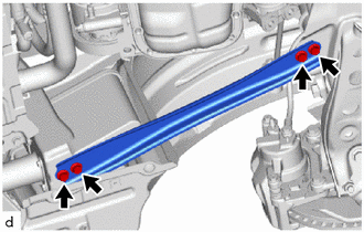
12. REMOVE REAR SIDE RAIL REINFORCEMENT SUB-ASSEMBLY LH
|
(a) Remove the 4 bolts and rear side rail reinforcement sub-assembly LH from the front suspension crossmember sub-assembly and vehicle body. |
|
13. REMOVE REAR SIDE RAIL REINFORCEMENT SUB-ASSEMBLY RH
HINT:
Perform the same procedure as for the LH side.
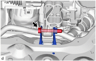
14. SEPARATE FRONT STABILIZER LINK ASSEMBLY LH
|
(a) Remove the nut and front stabilizer link assembly LH from the front shock absorber assembly. NOTICE: Do not damage the boot of the ball joint. HINT: If the ball joint turns together with the nut, use a 6 mm hexagon socket wrench to hold the stud bolt. |
|
.png)
15. SEPARATE FRONT STABILIZER LINK ASSEMBLY RH
HINT:
Perform the same procedure as for the LH side.
16. SEPARATE TIE ROD END SUB-ASSEMBLY LH
Click here
17. SEPARATE TIE ROD END SUB-ASSEMBLY RH
HINT:
Perform the same procedure as for the LH side.
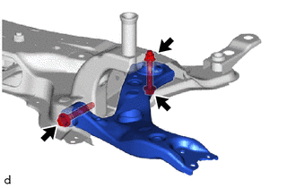
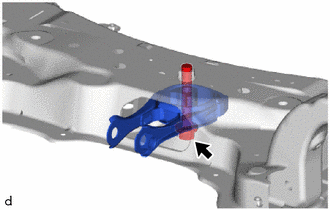
18. SEPARATE FRONT LOWER NO. 1 SUSPENSION ARM SUB-ASSEMBLY LH
|
(a) Remove the bolt and 2 nuts and separate the front lower No. 1 suspension arm sub-assembly from the front lower ball joint assembly. |
|
.png)
19. SEPARATE FRONT LOWER NO. 1 SUSPENSION ARM SUB-ASSEMBLY RH
HINT:
Perform the same procedure as for the LH side.
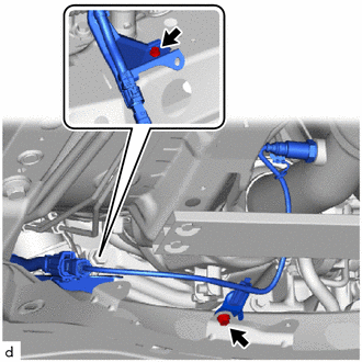
20. REMOVE FRONT SUSPENSION CROSSMEMBER SUB-ASSEMBLY
|
(a) Remove the 2 bolts and separate the 2 wire harness clamp brackets from the front suspension crossmember sub-assembly. |
|
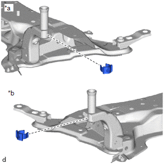
(b) Using a transmission jack and a wooden block, support the engine assembly with transaxle.
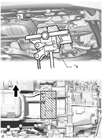
|
*a |
Transmission Jack |
|
*b |
Wooden Block |
.png) |
Front of the Vehicle |
.png) |
Wooden block placement location |
CAUTION:
- Support the engine assembly with transaxle until the front suspension crossmember sub-assembly is installed.
- If the support is removed before the front suspension crossmember sub-assembly is installed, the engine assembly with transaxle may drop.
|
(c) Remove the bolt and separate the engine moving control rod. |
|
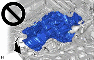
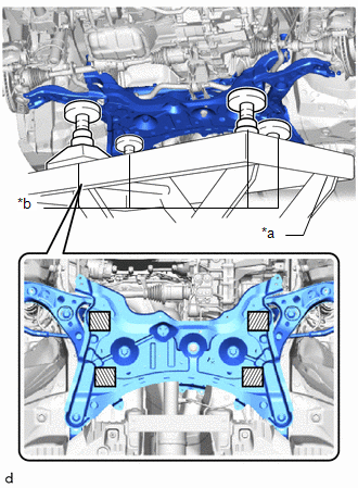
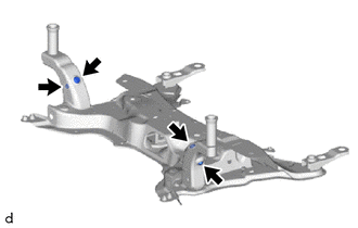
(d) Support the front suspension crossmember sub-assembly with an engine lifter using 4 attachments or equivalent tools as shown in the illustration.
|
*a |
Engine Lifter |
|
*b |
Attachment |
|
|
Attachment placement location |
CAUTION:
- The front suspension crossmember sub-assembly is a very heavy component. Make sure that it is supported securely.
- If the front suspension crossmember sub-assembly is not securely supported, it may drop, resulting in serious injury.
.png)
NOTICE:
Use attachments to keep the front suspension crossmember sub-assembly level.
(e) Remove the 6 bolts and front suspension crossmember sub-assembly.
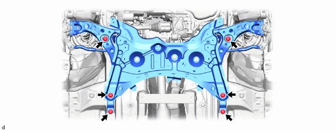
(f) Slowly lower the front suspension crossmember sub-assembly.
NOTICE:
When lowering the front suspension crossmember sub-assembly, be careful not to damage the vehicle body or other components installed to the vehicle.
21. REMOVE STEERING LINK ASSEMBLY
|
(a) Remove the 2 bolts, 2 nuts and steering link assembly from the front suspension crossmember sub-assembly. NOTICE: Because the nut has its own stopper, do not turn the nut. Loosen the bolt with the nut secured. |
|
.png)
22. REMOVE FRONT NO. 1 STABILIZER BRACKET LH
Click here
23. REMOVE FRONT NO. 1 STABILIZER BRACKET RH
HINT:
Perform the same procedure as for the LH side.
24. REMOVE FRONT STABILIZER BAR
Click here
25. REMOVE FRONT LOWER NO. 1 SUSPENSION ARM SUB-ASSEMBLY LH
|
(a) Remove the 2 bolts, nut and front lower No. 1 suspension arm sub-assembly LH from the front suspension crossmember sub-assembly. NOTICE: Because the nut has its own stopper, do not turn the nut. Loosen the bolt with the nut secured. |
|
26. REMOVE FRONT LOWER NO. 1 SUSPENSION ARM SUB-ASSEMBLY RH
HINT:
Perform the same procedure as for the LH side.
27. REMOVE ENGINE MOVING CONTROL ROD
|
(a) Remove the bolt and engine moving control rod from the front suspension crossmember sub-assembly. |
|
28. REMOVE FRONT SUSPENSION MEMBER PLATE
|
(a) Remove the 2 front suspension member plates from the front suspension crossmember sub-assembly. |
|
29. REMOVE HOLE PLUG
|
(a) Remove the 4 hole plugs from the front suspension crossmember sub-assembly. HINT: There are 2 different shapes of hole plug. |
|
 Installation
INSTALLATION
PROCEDURE
1. INSTALL HOLE PLUG
(a) Install the 4 hole plugs to the front suspension crossmember sub-assembly.
HINT:
There are 2 different shapes of hole plug.
2. INSTALL FRONT SUSPE ...

Other materials:
Toyota CH-R Service Manual > Power Steering System: EPS Warning Light Circuit
DESCRIPTION
If the power steering ECU assembly detects a malfunction, the power steering
ECU assembly stores a DTC and illuminates the EPS warning light.
WIRING DIAGRAM
CAUTION / NOTICE / HINT
NOTICE:
If the power steering ECU assembly has been replaced, perform assist
map writi ...
Toyota CH-R Service Manual > Vacuum Pump: Components
COMPONENTS
ILLUSTRATION
*1
ENGINE WIRE
*2
NO. 2 CYLINDER HEAD COVER
N*m (kgf*cm, ft.*lbf): Specified torque
-
-
ILLUSTRATION
*1
UNION TO CONNECTOR TUBE HOSE
* ...
Toyota C-HR (AX20) 2023-2026 Owner's Manual
Toyota CH-R Owners Manual
- For safety and security
- Instrument cluster
- Operation of each component
- Driving
- Interior features
- Maintenance and care
- When trouble arises
- Vehicle specifications
- For owners
Toyota CH-R Service Manual
- Introduction
- Maintenance
- Audio / Video
- Cellular Communication
- Navigation / Multi Info Display
- Park Assist / Monitoring
- Brake (front)
- Brake (rear)
- Brake Control / Dynamic Control Systems
- Brake System (other)
- Parking Brake
- Axle And Differential
- Drive Shaft / Propeller Shaft
- K114 Cvt
- 3zr-fae Battery / Charging
- Networking
- Power Distribution
- Power Assist Systems
- Steering Column
- Steering Gear / Linkage
- Alignment / Handling Diagnosis
- Front Suspension
- Rear Suspension
- Tire / Wheel
- Tire Pressure Monitoring
- Door / Hatch
- Exterior Panels / Trim
- Horn
- Lighting (ext)
- Mirror (ext)
- Window / Glass
- Wiper / Washer
- Door Lock
- Heating / Air Conditioning
- Interior Panels / Trim
- Lighting (int)
- Meter / Gauge / Display
- Mirror (int)
- Power Outlets (int)
- Pre-collision
- Seat
- Seat Belt
- Supplemental Restraint Systems
- Theft Deterrent / Keyless Entry

0.009