Toyota CH-R Service Manual: Engine/Power Switch Malfunction (B2278)
DESCRIPTION
This DTC is stored when the SSW1 contact signal and SSW2 contact signal, which are detected when the engine switch is operated, do not match.
|
DTC No. |
Detection Item |
DTC Detection Condition |
Trouble Area |
Note |
|---|---|---|---|---|
|
B2278 |
Engine/Power Switch Malfunction |
When the engine switch is operated, the SSW1 contact signal and SSW2 contact signal do not match (1-trip detection logic*). |
|
|
- *: Only detected while a malfunction is present.
|
Vehicle Condition when Malfunction Detected |
Fail-safe Function when Malfunction Detected |
|---|---|
|
If either the SSW1 contact signal or SSW2 contact signal is stuck on, the power source mode cannot be changed by pressing the engine switch. If either the SSW1 contact signal or SSW2 contact signal is stuck off, emergency stop by pressing and holding the engine switch for 2 seconds or more cannot be operated. |
- |
|
DTC No. |
Data List and Active Test |
|---|---|
|
B2278 |
Power Source Control
|
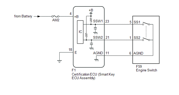
WIRING DIAGRAM
CAUTION / NOTICE / HINT
NOTICE:
- When using the Techstream with the engine switch off, connect the Techstream to the DLC3 and turn a courtesy light switch on and off at intervals of 1.5 seconds or less until communication between the Techstream and the vehicle begins. Then select the vehicle type under manual mode and enter the following menus: Body Electrical / Smart Key. While using the Techstream, periodically turn a courtesy light switch on and off at intervals of 1.5 seconds or less to maintain communication between the Techstream and the vehicle.
- The smart key system (for Start Function) uses the LIN communication
system and CAN communication system. Inspect the communication function
by following How to Proceed with Troubleshooting. Troubleshoot the smart
key system (for Start Function) after confirming that the communication
systems are functioning properly.
Click here
.gif)
- Inspect the fuses of circuits related to this system before performing the following procedure.
- Before replacing the certification ECU (smart key ECU assembly), refer
to smart key system (for Start Function) Precaution.
Click here
- After repair, confirm that no DTCs are output by performing "DTC Output Confirmation Operation".
HINT:
When the cable is disconnected and reconnected to the negative (-) battery terminal, the power source mode returns to the state it was in before the cable was disconnected.
PROCEDURE
|
1. |
READ VALUE USING TECHSTREAM (START SWITCH1, START SWITCH2) |
(a) Connect the Techstream to the DLC3.
(b) Turn the engine switch on (IG).
(c) Turn the Techstream on.
(d) Enter the following menus: Body Electrical / Power Source Control / Data List.
(e) Read the Data List according to the display on the Techstream.
Body Electrical > Power Source Control > Data List|
Tester Display |
Measurement Item |
Range |
Normal Condition |
Diagnostic Note |
|---|---|---|---|---|
|
Start Switch1 |
Engine switch 1 status |
OFF or ON |
OFF: Engine switch not pressed ON: Engine switch pressed |
|
|
Start Switch2 |
Engine switch 2 status |
OFF or ON |
OFF: Engine switch not pressed ON: Engine switch pressed |
|
|
Tester Display |
|---|
|
Start Switch1 |
|
Start Switch2 |
OK:
The Techstream display changes correctly in response to the engine switch operation.
| NG | .gif) |
GO TO STEP 3 |
|
.gif)
|
2. |
READ VALUE USING TECHSTREAM (START SWITCH1, START SWITCH2) |
(a) Connect the Techstream to the DLC3.
(b) Turn the engine switch on (IG).
(c) Turn the Techstream on.
(d) Enter the following menus: Body Electrical / Power Source Control / Data List.
(e) According to the display on the Techstream, read the Data List while wiggling the wire harness.
Body Electrical > Power Source Control > Data List|
Tester Display |
Measurement Item |
Range |
Normal Condition |
Diagnostic Note |
|---|---|---|---|---|
|
Start Switch1 |
Engine switch 1 status |
OFF or ON |
OFF: Engine switch not pressed ON: Engine switch pressed |
|
|
Start Switch2 |
Engine switch 2 status |
OFF or ON |
OFF: Engine switch not pressed ON: Engine switch pressed |
|
|
Tester Display |
|---|
|
Start Switch1 |
|
Start Switch2 |
OK:
The Techstream display changes correctly in response to the engine switch operation.
| OK | |
USE SIMULATION METHOD TO CHECK |
| NG | |
REPAIR OR REPLACE HARNESS OR CONNECTOR |
|
3. |
CHECK HARNESS AND CONNECTOR (POWER SOURCE) |
Click here
| NG | |
REPAIR OR REPLACE HARNESS OR CONNECTOR |
|
|
4. |
CHECK HARNESS AND CONNECTOR (GROUND) |
Click here
| NG | |
REPAIR OR REPLACE HARNESS OR CONNECTOR |
|
|
5. |
CHECK HARNESS AND CONNECTOR (CERTIFICATION ECU (SMART KEY ECU ASSEMBLY) - ENGINE SWITCH) |
(a) Disconnect the F1 certification ECU (smart key ECU assembly) connector.
(b) Disconnect the F59 engine switch connector.
(c) Measure the resistance according to the value(s) in the table below.
Standard Resistance:
|
Tester Connection |
Condition |
Specified Condition |
|---|---|---|
|
F1-23 (SSW1) - F59-5 (SS1) |
Always |
Below 1 Ω |
|
F1-21 (SSW2) - F59-1 (SS2) |
Always |
Below 1 Ω |
|
F1-11 (AGND) - F59-6 (AGND) |
Always |
Below 1 Ω |
|
F1-23 (SSW1) or F59-5 (SS1) - Body ground |
Always |
10 kΩ or higher |
|
F1-21 (SSW2) or F59-1 (SS2) - Body ground |
Always |
10 kΩ or higher |
|
F1-11 (AGND) or F59-6 (AGND) - Body ground |
Always |
10 kΩ or higher |
| NG | |
REPAIR OR REPLACE HARNESS OR CONNECTOR |
|
|
6. |
INSPECT ENGINE SWITCH |
(a) Remove the engine switch.
Click here
(b) Inspect the engine switch.
Click here
| OK | |
REPLACE CERTIFICATION ECU (SMART KEY ECU ASSEMBLY) |
| NG | |
REPLACE ENGINE SWITCH |
 Detecting Vehicle Submersion (B2277)
DESCRIPTION
This DTC is stored when a malfunction in the water submersion detection circuit
inside the certification ECU (smart key ECU assembly) is detected.
DTC No.
Detecti ...
 Vehicle Speed Signal Malfunction (B2282,B2283)
DESCRIPTION
DTC B2282 is stored when the vehicle speed signal sent by the combination meter
assembly via direct line and the vehicle speed signal sent via CAN communication
do not match.
DTC B22 ...
Other materials:
Toyota CH-R Service Manual > Vehicle Stability Control System: Acceleration Sensor Stuck Malfunction (C1243,C1245)
DESCRIPTION
The skid control ECU (brake actuator assembly) receives signals from the yaw
rate and acceleration sensor (airbag sensor assembly) via CAN communication.
The airbag sensor assembly has a built-in yaw rate and acceleration sensor and
detects the vehicle's condition using 2 circu ...
Toyota CH-R Service Manual > Vehicle Stability Control System: Check For Intermittent Problems
CHECK FOR INTERMITTENT PROBLEMS
CHECK FOR INTERMITTENT PROBLEMS
HINT:
A momentary interruption (open circuit) in the connectors and/or wire harness
between the sensors and ECUs can be detected using the Data List function of the
Techstream.
(a) Turn the ignition switch off.
(b) Connect the ...
Toyota C-HR (AX20) 2023-2026 Owner's Manual
Toyota CH-R Owners Manual
- For safety and security
- Instrument cluster
- Operation of each component
- Driving
- Interior features
- Maintenance and care
- When trouble arises
- Vehicle specifications
- For owners
Toyota CH-R Service Manual
- Introduction
- Maintenance
- Audio / Video
- Cellular Communication
- Navigation / Multi Info Display
- Park Assist / Monitoring
- Brake (front)
- Brake (rear)
- Brake Control / Dynamic Control Systems
- Brake System (other)
- Parking Brake
- Axle And Differential
- Drive Shaft / Propeller Shaft
- K114 Cvt
- 3zr-fae Battery / Charging
- Networking
- Power Distribution
- Power Assist Systems
- Steering Column
- Steering Gear / Linkage
- Alignment / Handling Diagnosis
- Front Suspension
- Rear Suspension
- Tire / Wheel
- Tire Pressure Monitoring
- Door / Hatch
- Exterior Panels / Trim
- Horn
- Lighting (ext)
- Mirror (ext)
- Window / Glass
- Wiper / Washer
- Door Lock
- Heating / Air Conditioning
- Interior Panels / Trim
- Lighting (int)
- Meter / Gauge / Display
- Mirror (int)
- Power Outlets (int)
- Pre-collision
- Seat
- Seat Belt
- Supplemental Restraint Systems
- Theft Deterrent / Keyless Entry

0.0092