Toyota CH-R Service Manual: Vehicle Speed Signal Malfunction (B2282,B2283)
DESCRIPTION
DTC B2282 is stored when the vehicle speed signal sent by the combination meter assembly via direct line and the vehicle speed signal sent via CAN communication do not match.
DTC B2283 is stored when a malfunction in the vehicle speed sensor is detected.
|
DTC No. |
Detection Item |
DTC Detection Condition |
Trouble Area |
Note |
|---|---|---|---|---|
|
B2282 |
Vehicle Speed Signal Malfunction |
The vehicle speed signal sent by the combination meter assembly via direct line and the vehicle speed signal sent via CAN communication do not match. (1-trip detection logic*) |
|
|
|
B2283 |
Vehicle Speed Sensor Malfunction |
Either of the following malfunctions is detected (a vehicle speed sensor malfunction is detected) (1-trip detection logic*):
|
|
DTC Output Confirmation Operation:
|
- *: Only detected while a malfunction is present and the engine switch is on (IG).
|
Vehicle Condition |
|||
|---|---|---|---|
|
Pattern 1 |
Pattern 2 |
||
|
Diagnosis Condition |
|
○ |
○ |
|
Malfunction Status |
Excessive deceleration is detected |
○ |
- |
|
Engine speed linked detection |
- |
○ |
|
|
Detection Time |
- |
- |
|
|
Number of Trips |
1 trip |
1 trip |
|
HINT:
DTC will be output when conditions for either of the patterns in the table above are met.
Vehicle Condition and Fail-safe Function when Malfunction Detected|
DTC Code |
Vehicle Condition when Malfunction Detected |
Fail-safe Function when Malfunction Detected |
|---|---|---|
|
B2282 |
|
- |
|
B2283 |
|
Steering lock motor operation is prohibited. |
|
DTC No. |
Data List and Active Test |
|---|---|
|
B2282 B2283 |
Power Source Control
Starting Control
Combination Meter
|
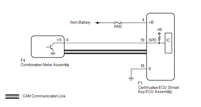
WIRING DIAGRAM
CAUTION / NOTICE / HINT
NOTICE:
- When using the Techstream with the engine switch off, connect the Techstream to the DLC3 and turn a courtesy light switch on and off at intervals of 1.5 seconds or less until communication between the Techstream and the vehicle begins. Then select the vehicle type under manual mode and enter the following menus: Body Electrical / Smart Key. While using the Techstream, periodically turn a courtesy light switch on and off at intervals of 1.5 seconds or less to maintain communication between the Techstream and the vehicle.
- The smart key system (for Start Function) uses the LIN communication
system and CAN communication system. Inspect the communication function
by following How to Proceed with Troubleshooting. Troubleshoot the smart
key system (for Start Function) after confirming that the communication
systems are functioning properly.
Click here
.gif)
- Inspect the fuses of circuits related to this system before performing the following procedure.
- Before replacing the certification ECU (smart key ECU assembly), refer
to smart key system (for Start Function) Precaution.
Click here
- After repair, confirm that no DTCs are output by performing "DTC Output Confirmation Operation".
HINT:
When the cable is disconnected and reconnected to the negative (-) battery terminal, the power source mode returns to the state it was in before the cable was disconnected.
PROCEDURE
|
1. |
READ VALUE USING TECHSTREAM (VEHICLE SPEED METER) |
(a) Connect the Techstream to the DLC3.
(b) Turn the engine switch on (IG).
(c) Turn the Techstream on.
(d) Enter the following menus: Body Electrical / Combination Meter / Data List.
(e) Read the Data List according to the display on the Techstream.
Body Electrical > Combination Meter > Data List|
Tester Display |
Measurement Item |
Range |
Normal Condition |
Diagnostic Note |
|---|---|---|---|---|
|
Vehicle Speed Meter |
Vehicle speed |
Min.: 0, Max.: 255 |
Almost same as actual vehicle speed (Speedometer tester) |
- |
|
Tester Display |
|---|
|
Vehicle Speed Meter |
HINT:
Using a speedometer tester, check the actual vehicle speed and the vehicle speed displayed on the Techstream.
OK:
Vehicle speed displayed on the Techstream is almost the same as the actual vehicle speed measured using a speedometer tester.
| NG | .gif) |
GO TO METER / GAUGE SYSTEM (Speedometer Malfunction)
|
|
.gif)
|
2. |
READ VALUE USING TECHSTREAM (VEHICLE SPEED SIGNAL) |
(a) Enter the following menus: Body Electrical / Power Source Control / Data List.
(b) Read the Data List according to the display on the Techstream.
Body Electrical > Power Source Control > Data List|
Tester Display |
Measurement Item |
Range |
Normal Condition |
Diagnostic Note |
|---|---|---|---|---|
|
Vehicle Speed Signal |
Vehicle being driven or stopped |
Stop or Run |
Stop: Vehicle stopped Run: Vehicle being driven at 5 km/h (3 mph) or more |
- |
|
Tester Display |
|---|
|
Vehicle Speed Signal |
OK:
The Techstream display changes correctly in response to the vehicle condition.
| OK | |
GO TO METER / GAUGE SYSTEM (HOW TO PROCEED WITH TROUBLESHOOTING) |
|
|
3. |
CHECK HARNESS AND CONNECTOR (POWER SOURCE) |
Click here
| NG | |
REPAIR OR REPLACE HARNESS OR CONNECTOR IN CIRCUIT CONNECTED TO POWER SOURCE |
|
|
4. |
CHECK HARNESS AND CONNECTOR (GROUND) |
Click here
| NG | |
REPAIR OR REPLACE HARNESS OR CONNECTOR |
|
|
5. |
CHECK HARNESS AND CONNECTOR (CERTIFICATION ECU (SMART KEY ECU ASSEMBLY) - COMBINATION METER ASSEMBLY) |
(a) Disconnect the F1 certification ECU (smart key ECU assembly) connector.
(b) Disconnect the F4 combination meter assembly connector.
(c) Measure the resistance according to the value(s) in the table below.
Standard Resistance:
|
Tester Connection |
Condition |
Specified Condition |
|---|---|---|
|
F1-19 (SPD) - F4-6 (+S) |
Always |
Below 1 Ω |
|
F1-19 (SPD) or F4-6 (+S) - Body ground |
Always |
10 kΩ or higher |
| NG | |
REPAIR OR REPLACE HARNESS OR CONNECTOR |
|
|
6. |
CHECK CERTIFICATION ECU (SMART KEY ECU ASSEMBLY) |
(a) Reconnect the F1 certification ECU (smart key ECU assembly) connector.
(b) Reconnect the F4 combination meter assembly connector.
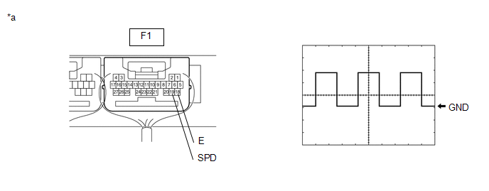
(c) Using an oscilloscope, check the waveform.
|
*a |
Component with harness connected (Certification ECU (Smart Key ECU Assembly)) |
- |
- |
|
Tester Connection |
Condition |
Tool Setting |
Specified Condition |
|---|---|---|---|
|
F1-19 (SPD) - F1-18 (E) |
Vehicle being driven at approx. 5 km/h (3 mph) |
5 V/DIV., 20 ms./DIV. |
Pulse generation |
HINT:
The wavelength becomes shorter as the vehicle speed increases.
| OK | |
REPLACE CERTIFICATION ECU (SMART KEY ECU ASSEMBLY) |
| NG | |
GO TO METER / GAUGE SYSTEM (Speed Signal Circuit)
|
 Engine/Power Switch Malfunction (B2278)
DESCRIPTION
This DTC is stored when the SSW1 contact signal and SSW2 contact signal, which
are detected when the engine switch is operated, do not match.
DTC No.
Detection It ...
 System Voltage or GND Energization Malfunction (B228B)
DESCRIPTION
This DTC is stored when there is a malfunction in the certification ECU (smart
key ECU assembly) battery power supply circuit or ground circuit.
DTC No.
Detection ...
Other materials:
Toyota CH-R Service Manual > Outer Rear View Mirror: Reassembly
REASSEMBLY
CAUTION / NOTICE / HINT
HINT:
Use the same procedure for the RH side and LH side.
The following procedure is for the LH side.
PROCEDURE
1. INSTALL NO. 2 OUTER MIRROR COVER (w/ Illumination)
(a) Engage the claws to install the No. 2 outer mirror cover as shown in th ...
Toyota CH-R Service Manual > Front Brake Flexible Hose: Components
COMPONENTS
ILLUSTRATION
*1
FRONT FLEXIBLE HOSE
*2
GASKET
*3
BRAKE LINE
*4
FRONT SPEED SENSOR
*5
UNION BOLT
-
-
Tightening torq ...
Toyota C-HR (AX20) 2023-2026 Owner's Manual
Toyota CH-R Owners Manual
- For safety and security
- Instrument cluster
- Operation of each component
- Driving
- Interior features
- Maintenance and care
- When trouble arises
- Vehicle specifications
- For owners
Toyota CH-R Service Manual
- Introduction
- Maintenance
- Audio / Video
- Cellular Communication
- Navigation / Multi Info Display
- Park Assist / Monitoring
- Brake (front)
- Brake (rear)
- Brake Control / Dynamic Control Systems
- Brake System (other)
- Parking Brake
- Axle And Differential
- Drive Shaft / Propeller Shaft
- K114 Cvt
- 3zr-fae Battery / Charging
- Networking
- Power Distribution
- Power Assist Systems
- Steering Column
- Steering Gear / Linkage
- Alignment / Handling Diagnosis
- Front Suspension
- Rear Suspension
- Tire / Wheel
- Tire Pressure Monitoring
- Door / Hatch
- Exterior Panels / Trim
- Horn
- Lighting (ext)
- Mirror (ext)
- Window / Glass
- Wiper / Washer
- Door Lock
- Heating / Air Conditioning
- Interior Panels / Trim
- Lighting (int)
- Meter / Gauge / Display
- Mirror (int)
- Power Outlets (int)
- Pre-collision
- Seat
- Seat Belt
- Supplemental Restraint Systems
- Theft Deterrent / Keyless Entry

0.0069