
Toyota CH-R Service Manual: System Voltage or GND Energization Malfunction (B228B)
DESCRIPTION
This DTC is stored when there is a malfunction in the certification ECU (smart key ECU assembly) battery power supply circuit or ground circuit.
|
DTC No. |
Detection Item |
DTC Detection Condition |
Trouble Area |
Note |
|---|---|---|---|---|
|
B228B |
System Voltage or GND Energization Malfunction |
Either of the following malfunctions is detected (a vehicle speed sensor malfunction is detected) (1-trip detection logic*):
|
|
|
- *: Only detected while a malfunction is present and the engine switch is on (IG).
|
Vehicle Condition |
|||
|---|---|---|---|
|
Pattern 1 |
Pattern 2 |
||
|
Diagnosis Condition |
Drive the vehicle. |
○ |
○ |
|
Malfunction Status |
A malfunction is detected in the certification ECU (smart key ECU assembly) battery power supply circuit. |
○ |
- |
|
A malfunction is detected in the certification ECU (smart key ECU assembly) ground circuit. |
- |
○ |
|
|
Detection Time |
- |
- |
|
|
Number of Trips |
1 trip |
1 trip |
|
HINT:
DTC will be output when conditions for either of the patterns in the table above are met.
Vehicle Condition and Fail-safe Function when Malfunction Detected|
Vehicle Condition when Malfunction Detected |
Fail-safe Function when Malfunction Detected |
|---|---|
|
The engine stopped while driving. |
- |
|
DTC No. |
Data List and Active Test |
|---|---|
|
B228B |
- |
WIRING DIAGRAM
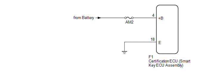
CAUTION / NOTICE / HINT
NOTICE:
- When using the Techstream with the engine switch off, connect the Techstream to the DLC3 and turn a courtesy light switch on and off at intervals of 1.5 seconds or less until communication between the Techstream and the vehicle begins. Then select the vehicle type under manual mode and enter the following menus: Body Electrical / Smart Key. While using the Techstream, periodically turn a courtesy light switch on and off at intervals of 1.5 seconds or less to maintain communication between the Techstream and the vehicle.
- The smart key system (for Start Function) uses the LIN communication
system and CAN communication system. Inspect the communication function
by following How to Proceed with Troubleshooting. Troubleshoot the smart
key system (for Start Function) after confirming that the communication
systems are functioning properly.
Click here
.gif)
- Inspect the fuses of circuits related to this system before performing the following procedure.
- After repair, confirm that no DTCs are output by performing "DTC Output Confirmation Operation".
HINT:
When the cable is disconnected and reconnected to the negative (-) battery terminal, the power source mode returns to the state it was in before the cable was disconnected.
PROCEDURE
|
1. |
CHECK HARNESS AND CONNECTOR (POWER SOURCE) |
Click here
| NG | .gif) |
REPAIR OR REPLACE HARNESS OR CONNECTOR IN CIRCUIT CONNECTED TO POWER SOURCE |
|
.gif)
|
2. |
CHECK HARNESS AND CONNECTOR (GROUND) |
Click here
| OK | |
END (TEMPORARY CONNECTION FAILURE IS SUSPECTED)
|
| NG | |
REPAIR OR REPLACE HARNESS OR CONNECTOR IN CIRCUIT CONNECTED TO POWER SOURCE |
 Vehicle Speed Signal Malfunction (B2282,B2283)
DESCRIPTION
DTC B2282 is stored when the vehicle speed signal sent by the combination meter
assembly via direct line and the vehicle speed signal sent via CAN communication
do not match.
DTC B22 ...
 Steering Lock Position Signal Circuit Malfunction (B2285)
DESCRIPTION
This DTC is stored when the steering lock position signal sent by the steering
lock ECU (steering lock actuator or upper bracket assembly) via direct line and
the steering lock positi ...
Other materials:
Toyota CH-R Service Manual > Rear Stabilizer Bar: Components
COMPONENTS
ILLUSTRATION
*1
REAR NO. 1 STABILIZER BAR BRACKET
*2
REAR STABILIZER BAR
*3
REAR STABILIZER BUSHING
*4
REAR STABILIZER LINK ASSEMBLY LH
*5
REAR STABILIZER LINK ASS ...
Toyota CH-R Service Manual > Maintenance: Front Wiper Rubber
Components
COMPONENTS
ILLUSTRATION
*1
FRONT WIPER BLADE
*2
FRONT WIPER RUBBER
Removal
REMOVAL
CAUTION / NOTICE / HINT
NOTICE:
Make sure to hold the front wiper arm while lifting it as lifting the front wiper
arm by the front wiper ...
Toyota CH-R Owners Manual
- For safety and security
- Instrument cluster
- Operation of each component
- Driving
- Interior features
- Maintenance and care
- When trouble arises
- Vehicle specifications
- For owners
Toyota CH-R Service Manual
- Introduction
- Maintenance
- Audio / Video
- Cellular Communication
- Navigation / Multi Info Display
- Park Assist / Monitoring
- Brake (front)
- Brake (rear)
- Brake Control / Dynamic Control Systems
- Brake System (other)
- Parking Brake
- Axle And Differential
- Drive Shaft / Propeller Shaft
- K114 Cvt
- 3zr-fae Battery / Charging
- Networking
- Power Distribution
- Power Assist Systems
- Steering Column
- Steering Gear / Linkage
- Alignment / Handling Diagnosis
- Front Suspension
- Rear Suspension
- Tire / Wheel
- Tire Pressure Monitoring
- Door / Hatch
- Exterior Panels / Trim
- Horn
- Lighting (ext)
- Mirror (ext)
- Window / Glass
- Wiper / Washer
- Door Lock
- Heating / Air Conditioning
- Interior Panels / Trim
- Lighting (int)
- Meter / Gauge / Display
- Mirror (int)
- Power Outlets (int)
- Pre-collision
- Seat
- Seat Belt
- Supplemental Restraint Systems
- Theft Deterrent / Keyless Entry

0.0096