Toyota CH-R Service Manual: Components
COMPONENTS
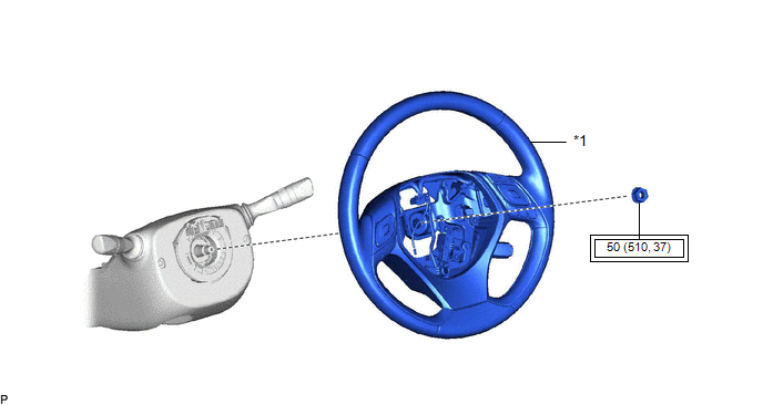
ILLUSTRATION
|
*1 |
STEERING WHEEL ASSEMBLY |
- |
- |
.png) |
Tightening torque for "Major areas involving basic vehicle performance such as moving/turning/stopping" : N*m (kgf*cm, ft.*lbf) |
- |
- |
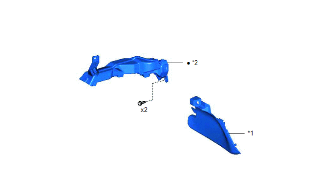
ILLUSTRATION
|
*1 |
CONSOLE BOX INSERT |
*2 |
NO. 1 AIR DUCT |
|
● |
Non-reusable part |
- |
- |
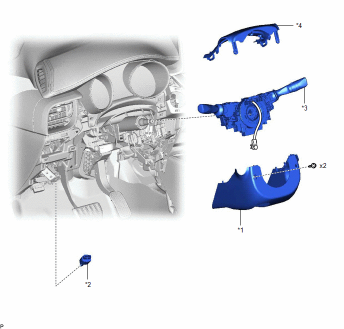
ILLUSTRATION
|
*1 |
LOWER STEERING COLUMN COVER SUB-ASSEMBLY |
*2 |
STOP LIGHT SWITCH ASSEMBLY |
|
*3 |
TURN SIGNAL SWITCH ASSEMBLY WITH SPIRAL CABLE SUB-ASSEMBLY |
*4 |
UPPER STEERING COLUMN COVER |
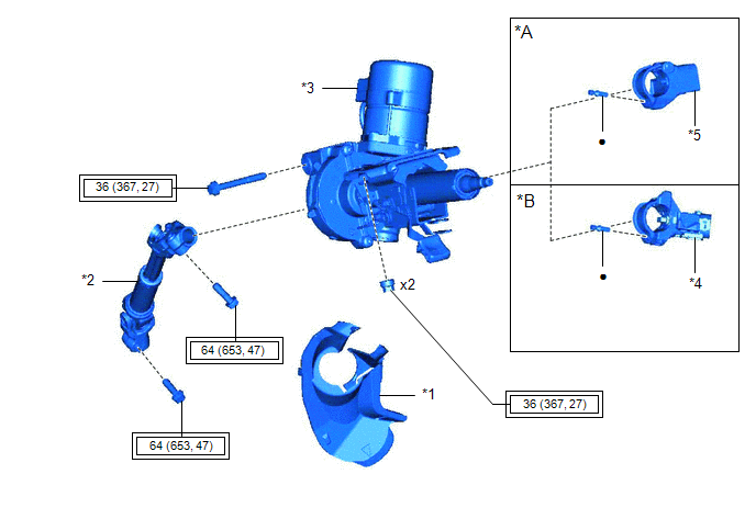
ILLUSTRATION
|
*A |
w/ Smart Key System |
*B |
w/o Smart Key System |
|
*1 |
COLUMN HOLE COVER SILENCER SHEET |
*2 |
NO. 2 STEERING INTERMEDIATE SHAFT ASSEMBLY |
|
*3 |
STEERING COLUMN ASSEMBLY |
*4 |
UPPER STEERING COLUMN BRACKET WITH SWITCH ASSEMBLY |
|
*5 |
STEERING LOCK ACTUATOR ASSEMBLY |
- |
- |
|
|
Tightening torque for "Major areas involving basic vehicle performance such as moving/turning/stopping" : N*m (kgf*cm, ft.*lbf) |
● |
Non-reusable part |
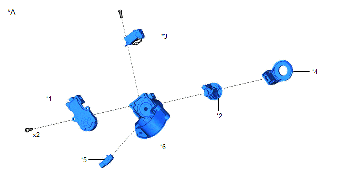
ILLUSTRATION
|
*A |
w/o Smart Key System |
- |
- |
|
*1 |
IGNITION OR STARTER SWITCH ASSEMBLY |
*2 |
IGNITION SWITCH LOCK CYLINDER ASSEMBLY |
|
*3 |
KEY INTERLOCK SOLENOID |
*4 |
TRANSPONDER KEY COIL |
|
*5 |
UN-LOCK WARNING SWITCH ASSEMBLY |
*6 |
UPPER STEERING COLUMN BRACKET ASSEMBLY |
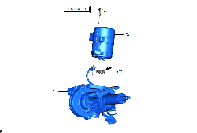
ILLUSTRATION
|
*1 |
ELECTRIC POWER STEERING MOTOR SHAFT DAMPER |
*2 |
POWER STEERING ECU ASSEMBLY |
|
*3 |
ELECTRIC POWER STEERING COLUMN SUB-ASSEMBLY |
- |
- |
|
|
Tightening torque for "Major areas involving basic vehicle performance such as moving/turning/stopping" : N*m (kgf*cm, ft.*lbf) |
● |
Non-reusable part |
.png) |
Grease |
- |
- |

 Removal
REMOVAL
CAUTION / NOTICE / HINT
The necessary procedures (adjustment, calibration, initialization, or registration)
that must be performed after parts are removed, installed, or replaced during th ...
Other materials:
Toyota CH-R Service Manual > Occupant Classification System: Lost Communication with Multi-axis Acceleration Sensor Module (U0125,U0129)
DESCRIPTION
The occupant detection ECU sends/receives signals to/from each ECU via CAN communication.
DTC No.
Detection Item
DTC Detection Condition
Trouble Area
U0125
Lost Communication with Multi-axis Acceleration Sensor Mod ...
Toyota CH-R Service Manual > General Maintenance: Inside Vehicle
INSIDE VEHICLE
These are maintenance and inspection items that are considered to be
the owner's responsibility.
The owner can do them or they can have them done at a service center.
These items include those that should be checked on a daily basis, those
that in most cases ...
Toyota C-HR (AX20) 2023-2026 Owner's Manual
Toyota CH-R Owners Manual
- For safety and security
- Instrument cluster
- Operation of each component
- Driving
- Interior features
- Maintenance and care
- When trouble arises
- Vehicle specifications
- For owners
Toyota CH-R Service Manual
- Introduction
- Maintenance
- Audio / Video
- Cellular Communication
- Navigation / Multi Info Display
- Park Assist / Monitoring
- Brake (front)
- Brake (rear)
- Brake Control / Dynamic Control Systems
- Brake System (other)
- Parking Brake
- Axle And Differential
- Drive Shaft / Propeller Shaft
- K114 Cvt
- 3zr-fae Battery / Charging
- Networking
- Power Distribution
- Power Assist Systems
- Steering Column
- Steering Gear / Linkage
- Alignment / Handling Diagnosis
- Front Suspension
- Rear Suspension
- Tire / Wheel
- Tire Pressure Monitoring
- Door / Hatch
- Exterior Panels / Trim
- Horn
- Lighting (ext)
- Mirror (ext)
- Window / Glass
- Wiper / Washer
- Door Lock
- Heating / Air Conditioning
- Interior Panels / Trim
- Lighting (int)
- Meter / Gauge / Display
- Mirror (int)
- Power Outlets (int)
- Pre-collision
- Seat
- Seat Belt
- Supplemental Restraint Systems
- Theft Deterrent / Keyless Entry

0.0146