Toyota CH-R Service Manual: Installation
INSTALLATION
PROCEDURE
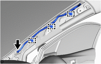
1. INSTALL ROOF HEADLINING
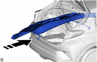
(a) Insert the roof headlining assembly into the cabin from the back door.
.png) |
Install in this Direction |
NOTICE:
- Check that the corners of the roof headlining are not folded, twisted or otherwise deformed and that none of the mounted parts have fallen off.
- Make sure that the roof headlining does not get caught on anything as it may become bent or damaged.
- Do not damage the roof headlining or vehicle interior.
|
(b) Engage the guides and set the roof headlining assembly. |
|
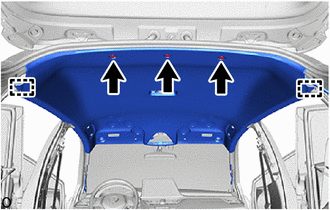
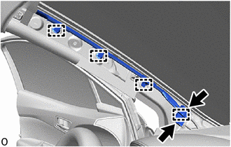
(c) Install the 3 clips.
|
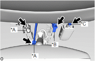
(d) for Windshield Glass Side: (1) Connect the each connector. |
|
|
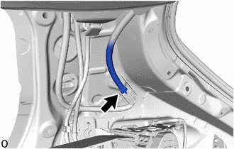
(e) for Rear Pillar RH Side: (1) Connect the connector. |
|
|
(f) for Front Pillar RH Side: (1) Engage the wire harness clamps. (2) Connect the connector. |
|
|
(g) for Front Pillar LH Side: (1) Engage the wire harness clamps. (2) Connect the 2 connectors. |
|
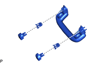
2. INSTALL ASSIST GRIP COVER
HINT:
Use the same procedures for the opposite side.
|
(a) Install the 2 assist grip covers and 2 clips to the assist grip sub-assembly. |
|
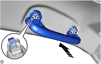
3. INSTALL ASSIST GRIP SUB-ASSEMBLY
HINT:
Use the same procedures for the opposite side.
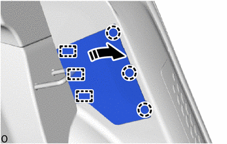
(a) Engage the clips to install the assist grip sub-assembly as shown in the illustration.
|
|
Install in this Direction |
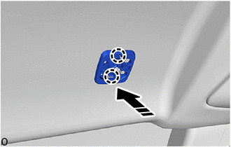
4. INSTALL VISOR HOLDER
HINT:
Use the same procedures for the opposite side.
(a) Engage the claws to install the base as shown in the illustration.
|
|
Install in this Direction |
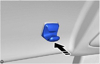
(b) Install the holder as shown in the illustration.
|
|
Install in this Direction |
5. INSTALL VISOR ASSEMBLY LH (w/o Vanity Light)
|
(a) Engage the guide to install the visor assembly LH. |
|
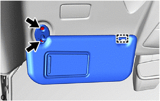
(b) Using a T10H "TORX" driver, install the 2 screws.
6. INSTALL VISOR ASSEMBLY RH (w/o Vanity Light)
HINT:
Use the same procedure as for the LH side.
7. INSTALL VISOR ASSEMBLY LH (w/ Vanity Light)
Click here .gif)
8. INSTALL VISOR ASSEMBLY RH (w/ Vanity Light)
HINT:
Use the same procedure as for the LH side.
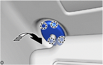
9. INSTALL VISOR BRACKET COVER
HINT:
Use the same procedures for the opposite side.
(a) Engage the claws to install the visor bracket cover as shown in the illustration.
|
|
Install in this Direction |
10. INSTALL NO. 1 ROOM LIGHT ASSEMBLY
Click here
11. INSTALL MAP LIGHT ASSEMBLY
Click here
12. INSTALL VANITY LIGHT ASSEMBLY (w/ Vanity Light)
Click here
13. INSTALL INNER REAR VIEW MIRROR STAY HOLDER COVER (w/o Lane Departure Alert System)
Click here
14. INSTALL NO. 1 FORWARD RECOGNITION COVER (w/ Lane Departure Alert System)
Click here
15. INSTALL NO. 2 FORWARD RECOGNITION COVER (w/ Lane Departure Alert System)
Click here
16. INSTALL RAIN SENSOR COVER (w/ Rain Sensor)
Click here
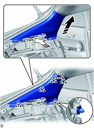
17. INSTALL ROOF SIDE INNER GARNISH ASSEMBLY LH
(a) When reusing the roof side inner garnish assembly LH:
(1) Install the 5 new clips to the roof side inner garnish assembly LH.
(b) Engage the guide and clips to install the roof side inner garnish assembly LH as shown in the illustration.
|
|
Install in this Direction (1) |
.png) |
Install in this Direction (2) |
18. INSTALL ROOF SIDE INNER GARNISH ASSEMBLY RH
HINT:
Use the same procedure as for the LH side.
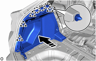
19. INSTALL DECK TRIM SIDE PANEL ASSEMBLY LH
(a) Connect the rear seat 3 point type outer belt assembly LH.
(b) Engage the clips and claws to install the deck trim side panel assembly LH as shown in the illustration.
|
|
Install in this Direction |
(c) w/ Hook:
(1) Install the luggage hold belt striker with the bolt.
(d) w/o Hook:
(1) Install the clip.
20. INSTALL DECK TRIM SIDE PANEL ASSEMBLY RH
HINT:
Use the same procedure as for the LH side.
21. INSTALL NO. 1 LUGGAGE COMPARTMENT LIGHT ASSEMBLY
Click here
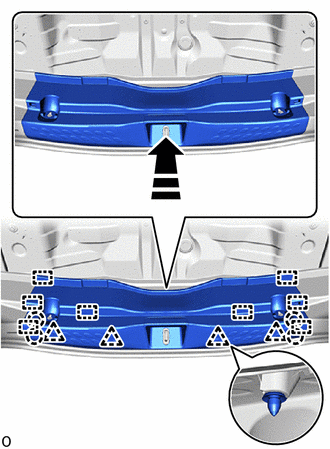
22. INSTALL DECK TRIM REAR COVER
(a) Engage the guides, claws and clips to install the deck trim rear cover as shown in the illustration.
|
|
Install in this Direction |
(b) w/ Hook:
(1) Install the 2 luggage hold belt strikers with 2 bolts.
(c) w/o Hook:
(1) Install the 2 clips.
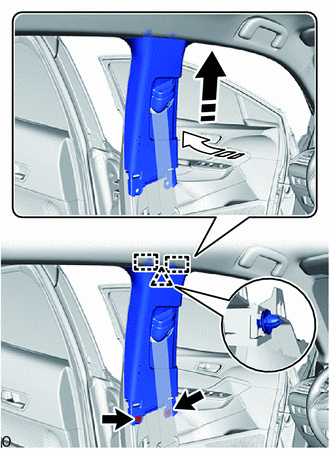
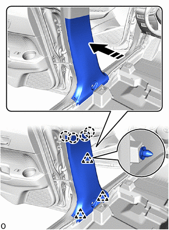
23. INSTALL CENTER PILLAR GARNISH ASSEMBLY LH
(a) When reusing the center pillar garnish assembly LH:
(1) Install a new clip to the center pillar garnish assembly LH.
(b) Engage the guides and clip to install the center pillar garnish assembly LH as shown in the illustration.
|
|
Install in this Direction (1) |
|
|
Install in this Direction (2) |
(c) Install the 2 clips.
24. INSTALL CENTER PILLAR GARNISH ASSEMBLY RH
HINT:
Use the same procedure as for the LH side.
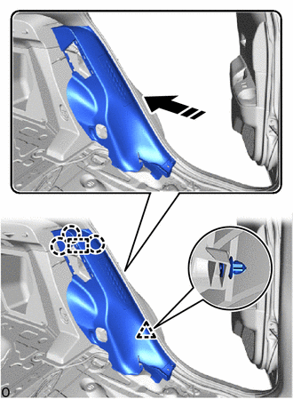
25. INSTALL CENTER PILLAR LOWER GARNISH LH
(a) Engage the clips and claws to install the center pillar lower garnish LH as shown in the illustration.
|
|
Install in this Direction |
26. INSTALL CENTER PILLAR LOWER GARNISH RH
HINT:
Use the same procedure as for the LH side.
27. CONNECT FRONT SEAT OUTER BELT ASSEMBLY LH
Click here
28. CONNECT FRONT SEAT OUTER BELT ASSEMBLY RH
HINT:
Use the same procedure as for the LH side.
29. INSTALL LAP BELT OUTER ANCHOR COVER
Click here
30. INSTALL REAR SEAT SIDE GARNISH LH (w/ Rear Seat Side Airbag)
(a) Engage the guide, claws and clip to install the rear seat side garnish LH as shown in the illustration.
|
|
Install in this Direction |
(b) Connect the airbag connector.
|
(c) Temporarily install the 2 bolts. |
|
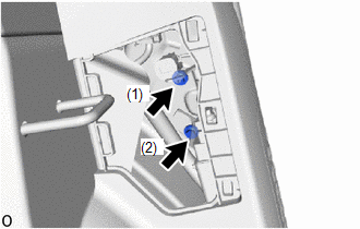
(d) Tighten the 2 bolts in the order shown in the illustration.
Torque:
8.0 N·m {82 kgf·cm, 71 in·lbf}
31. INSTALL REAR SEAT SIDE GARNISH RH (w/ Rear Seat Side Airbag)
HINT:
Use the same procedure as for the LH side.
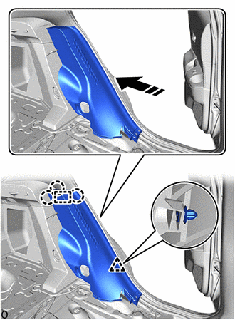
32. INSTALL REAR SEAT SIDE GARNISH LH (w/o Rear Seat Side Airbag)
(a) Engage the guide, claws and clip to install the rear seat side garnish LH as shown in the illustration.
|
|
Install in this Direction |
33. INSTALL REAR SEAT SIDE GARNISH RH (w/o Rear Seat Side Airbag)
HINT:
Use the same procedure as for the LH side.
34. INSTALL REAR PILLAR COVER LH (w/ Rear Seat Side Airbag)
(a) Engage the guides and claws to install the rear pillar cover LH as shown in the illustration.
|
|
Install in this Direction |
35. INSTALL REAR PILLAR COVER RH (w/ Rear Seat Side Airbag)
HINT:
Use the same procedure as for the LH side.
36. INSTALL REAR SEATBACK HINGE SUB-ASSEMBLY LH
(a) Install the rear seatback hinge sub-assembly LH with the bolt.
Torque:
18.1 N·m {185 kgf·cm, 13 ft·lbf}
37. INSTALL REAR SEATBACK HINGE SUB-ASSEMBLY RH
HINT:
Use the same procedure as for the LH side.
38. INSTALL REAR DOOR OPENING TRIM WEATHERSTRIP LH
Click here
39. INSTALL REAR DOOR OPENING TRIM WEATHERSTRIP RH
HINT:
Use the same procedure as for the LH side.
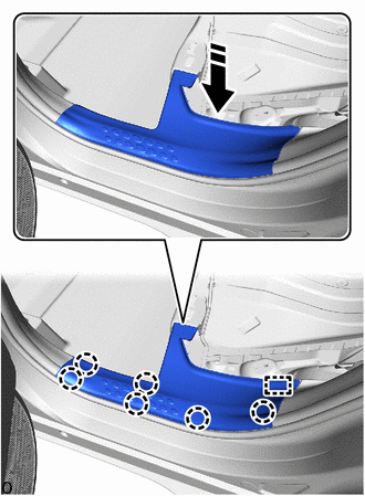
40. INSTALL REAR DOOR SCUFF PLATE LH (w/ Rear Seat Side Airbag)
(a) Engage the guide and claws to install the rear door scuff plate LH as shown in the illustration.
|
|
Install in this Direction |
41. INSTALL REAR DOOR SCUFF PLATE RH (w/ Rear Seat Side Airbag)
HINT:
Use the same procedure as for the LH side.
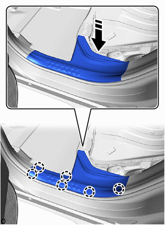
42. INSTALL REAR DOOR SCUFF PLATE LH (w/o Rear Seat Side Airbag)
(a) Engage the claws to install the rear door scuff plate LH as shown in the illustration.
|
|
Install in this Direction |
43. INSTALL REAR DOOR SCUFF PLATE RH (w/o Rear Seat Side Airbag)
HINT:
Use the same procedure as for the LH side.
44. INSTALL FRONT PILLAR GARNISH LH
Click here
45. INSTALL FRONT PILLAR GARNISH RH
HINT:
Use the same procedure as for the LH side.
46. INSTALL FRONT DOOR OPENING TRIM WEATHERSTRIP LH
Click here
47. INSTALL FRONT DOOR OPENING TRIM WEATHERSTRIP RH
HINT:
Use the same procedure as for the LH side.
48. INSTALL COWL SIDE TRIM BOARD LH
Click here
49. INSTALL COWL SIDE TRIM BOARD RH
HINT:
Use the same procedure as for the LH side.
50. INSTALL FRONT DOOR SCUFF PLATE LH
Click here
51. INSTALL FRONT DOOR SCUFF PLATE RH
HINT:
Use the same procedure as for the LH side.
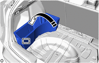
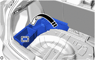
52. INSTALL DECK FLOOR BOX LH
(a) for Type A:
|
|
Install in this Direction |
(1) Engage the guide to install the deck floor box LH as shown in the illustration.
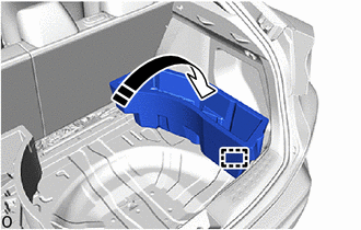
(b) for Type B:
|
|
Install in this Direction |
(1) Engage the guide to install the deck floor box LH as shown in the illustration.
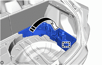
53. INSTALL DECK FLOOR BOX RH
(a) for Type A:
|
|
Install in this Direction |
(1) Engage the guide to install the deck floor box RH as shown in the illustration.
(b) for Type B:
|
|
Install in this Direction |
(1) Engage the guide to install the deck floor box RH as shown in the illustration.
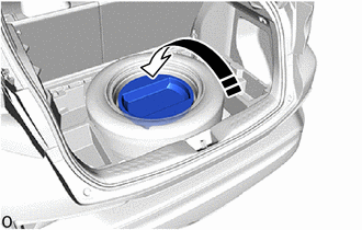
54. INSTALL SPARE WHEEL CUSHION
(a) for Type A:
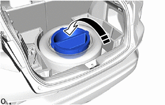
|
|
Install in this Direction |
(1) Install the spare wheel cushion as shown in the illustration.
(b) for Type B:
|
|
Install in this Direction |
(1) Install the spare wheel cushion as shown in the illustration.
55. INSTALL DECK BOARD ASSEMBLY
(a) for Type A:
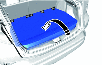
.png) |
Hook and Loop Fastener |
|
|
Install in this Direction |
(1) Install the deck board assembly as shown in the illustration.
(2) Engage the hook and loop fastener.
(b) for Type B:
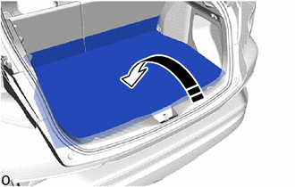
|
|
Install in this Direction |
(1) Install the deck board assembly as shown in the illustration.
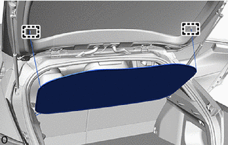
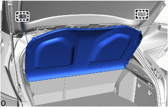
56. INSTALL TONNEAU COVER ASSEMBLY (w/ Tonneau Cover)
(a) Engage the guides to install the tonneau cover assembly as shown in the illustration.
|
|
Install in this Direction |
|
(b) Engage the hooks. |
|
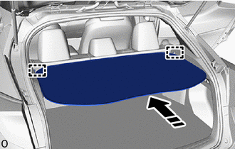
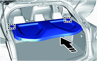
57. INSTALL PACKAGE TRAY TRIM PANEL ASSEMBLY (w/ Package Tray Trim)
(a) Engage the guides to install the package tray trim panel assembly as shown in the illustration.
|
|
Install in this Direction |
|
(b) Engage the hooks. |
|
58. INSTALL REAR SEAT ASSEMBLY
Click here
59. INSTALL FRONT SEAT ASSEMBLY LH
Click here
60. INSTALL FRONT SEAT ASSEMBLY RH
HINT:
Use the same procedure as for the LH side.
61. CONNECT CABLE TO NEGATIVE BATTERY TERMINAL
Click here
NOTICE:
When disconnecting the cable, some systems need to be initialized after the cable is reconnected.
Click here
62. INSPECT SRS WARNING LIGHT
Click here
 Reassembly
REASSEMBLY
PROCEDURE
1. INSTALL HEADLINING LIGHT CASE
(a) Align the markings on the roof headlining with the headlining light case
and install it using hot melt glue.
*a
...
 Lighting (int)
...
Other materials:
Toyota CH-R Service Manual > Lighting System: Hazard Warning Switch Circuit
DESCRIPTION
The combination meter assembly receives the hazard warning signal switch assembly
on signal and controls the operation of the hazard warning lights.
WIRING DIAGRAM
CAUTION / NOTICE / HINT
NOTICE:
When replacing the combination meter assembly, always replace it with a new one.
...
Toyota CH-R Service Manual > Door / Hatch: Back Door Weatherstrip
Components
COMPONENTS
ILLUSTRATION
*1
BACK DOOR WEATHERSTRIP
-
-
●
Non-reusable part
-
-
Removal
REMOVAL
PROCEDURE
1. REMOVE BACK DOOR WEATHERSTRIP
(a) Remove the back do ...
Toyota C-HR (AX20) 2023-2026 Owner's Manual
Toyota CH-R Owners Manual
- For safety and security
- Instrument cluster
- Operation of each component
- Driving
- Interior features
- Maintenance and care
- When trouble arises
- Vehicle specifications
- For owners
Toyota CH-R Service Manual
- Introduction
- Maintenance
- Audio / Video
- Cellular Communication
- Navigation / Multi Info Display
- Park Assist / Monitoring
- Brake (front)
- Brake (rear)
- Brake Control / Dynamic Control Systems
- Brake System (other)
- Parking Brake
- Axle And Differential
- Drive Shaft / Propeller Shaft
- K114 Cvt
- 3zr-fae Battery / Charging
- Networking
- Power Distribution
- Power Assist Systems
- Steering Column
- Steering Gear / Linkage
- Alignment / Handling Diagnosis
- Front Suspension
- Rear Suspension
- Tire / Wheel
- Tire Pressure Monitoring
- Door / Hatch
- Exterior Panels / Trim
- Horn
- Lighting (ext)
- Mirror (ext)
- Window / Glass
- Wiper / Washer
- Door Lock
- Heating / Air Conditioning
- Interior Panels / Trim
- Lighting (int)
- Meter / Gauge / Display
- Mirror (int)
- Power Outlets (int)
- Pre-collision
- Seat
- Seat Belt
- Supplemental Restraint Systems
- Theft Deterrent / Keyless Entry

0.0866