Toyota CH-R Service Manual: Reassembly
REASSEMBLY
PROCEDURE
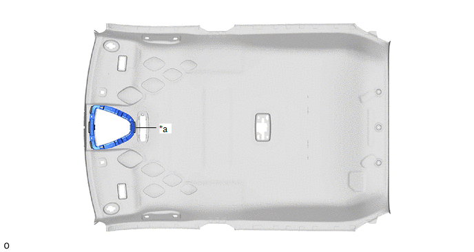
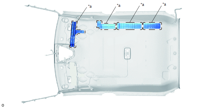
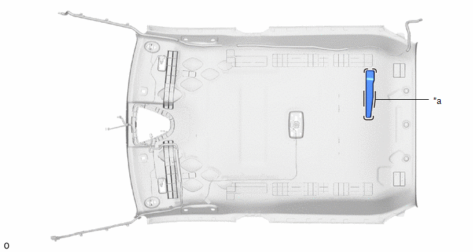
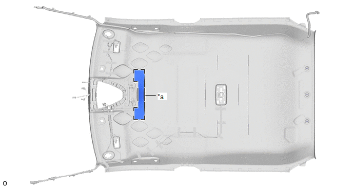
1. INSTALL HEADLINING LIGHT CASE
(a) Align the markings on the roof headlining with the headlining light case and install it using hot melt glue.
|
*a |
Marking |
- |
- |
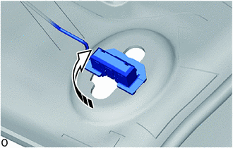
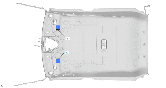
2. INSTALL NO. 2 ANTENNA CORD SUB-ASSEMBLY
Click here .gif)
3. INSTALL NO. 1 ROOF WIRE
(a) w/ Vanity Light:
.png) |
Install in this Direction |
(1) Turn the visor connectors approximately 90° clockwise to connect the visor connector as shown in the illustration.
HINT:
Use the same procedures for the opposite side.
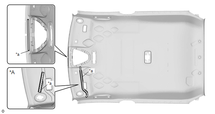
(b) Apply double-sided tape as shown in the illustration.
NOTICE:
Apply the supports with uniform loading, and without protruding from the roof headlining markings.
|
*A |
w/ Vanity Light |
- |
- |
|
*a |
Marking |
- |
- |
.png) |
Double-sided Tape |
- |
- |
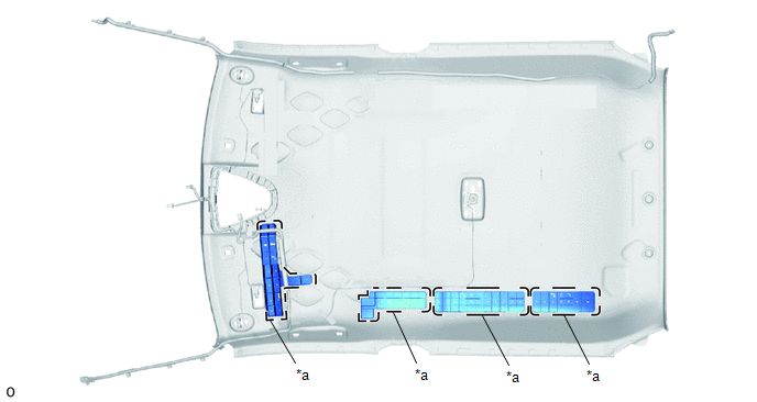
(c) Line up the No. 1 roof wire positioning tape and the roof headlining markings.
(d) Align new pieces of each adhesive tapes with the markings of the roof headlining and install them.
.png)
|
*A |
w/ Vanity Light |
- |
- |
(e) Engage each guide.
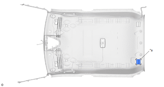
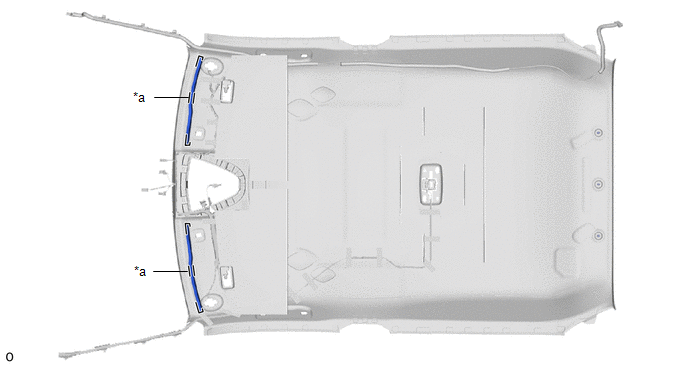
4. INSTALL SIDE RAIL REAR SPACER LH (for Cold Area)
(a) Align the markings on the roof headlining with the 4 side rail rear spacers LH and install them using hot melt glue.
|
*a |
Marking |
- |
- |
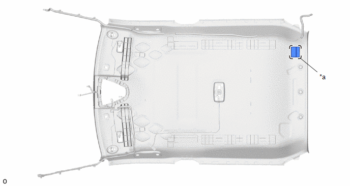
5. INSTALL SIDE RAIL REAR SPACER RH (for Cold Area)
(a) Align the markings on the roof headlining with the 4 side rail rear spacers RH and install them using hot melt glue.
|
*a |
Marking |
- |
- |
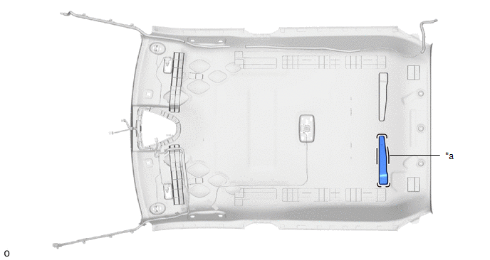
6. INSTALL NO. 2 ROOF HEADLINING PAD (for Cold Area)
(a) Align the markings on the roof headlining with the No. 2 roof headlining pad and install them using hot melt glue.
|
*a |
Marking |
- |
- |
7. INSTALL ROOF HEADLINING PAD (for Cold Area)
(a) Align the markings on the roof headlining with the roof headlining pad and install them using hot melt glue.
|
*a |
Marking |
- |
- |
8. INSTALL ROOF HEADLINING PAD LH (for Cold Area)
(a) Align the markings on the roof headlining with the roof headlining pad LH and install them using hot melt glue.
|
*a |
Marking |
- |
- |
9. INSTALL ROOF HEADLINING PAD RH (for Cold Area)
(a) Align the markings on the roof headlining with the roof headlining pad RH and install them using hot melt glue.
|
*a |
Marking |
- |
- |
10. INSTALL NO. 3 ROOF SILENCER PAD (for Cold Area)
(a) Align a new No. 3 roof silencer pad with the silencer markings on the roof headlining and install the No. 3 roof silencer pad using double-sided tape.
HINT:
Peel off the backing paper from the double-sided tape before installing the No. 3 roof silencer pad.
|
*a |
Marking |
- |
- |
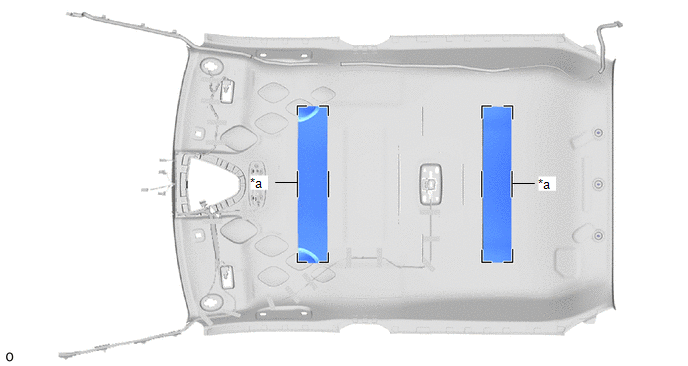
11. INSTALL ROOF SILENCER PAD
(a) Align the markings on the roof headlining with the 2 roof silencer pads and install them using hot melt glue.
|
*a |
Marking |
- |
- |
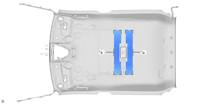
12. INSTALL NO. 2 ROOF SILENCER PAD
(a) Align the markings on the roof headlining with the 2 No. 2 roof silencer pads and install them using hot melt glue.
|
*a |
Marking |
- |
- |
13. INSTALL NO. 1 ROOF SILENCER PAD
(a) Align the markings on the roof headlining with the No. 1 roof silencer pad and install it using hot melt glue.
|
*a |
Marking |
- |
- |
14. INSTALL ROOF HEADLINING FORMING PAD (except Cold Area)
(a) Align the markings on the roof headlining with the 2 roof headlining forming pads and install them using hot melt glue.
|
*a |
Marking |
- |
- |
 Disassembly
DISASSEMBLY
PROCEDURE
1. REMOVE ROOF HEADLINING FORMING PAD (except Cold Area)
(a) Remove the 2 roof headlining forming pads.
2. REMOVE NO. 1 ROOF SILENCER PAD
(a) Remove the No. 1 roof silence ...
 Installation
INSTALLATION
PROCEDURE
1. INSTALL ROOF HEADLINING
(a) Insert the roof headlining assembly into the cabin from the back door.
Install in this Direction
NOTICE:
...
Other materials:
Toyota CH-R Service Manual > Tire Pressure Warning System: Terminals Of Ecu
TERMINALS OF ECU
CHECK TIRE PRESSURE WARNING ECU AND RECEIVER
(a) Disconnect the M23 tire pressure warning ECU and receiver connector and measure
the voltage or resistance on the wire harness side.
*a
Front view of wire harness connector
(to Tire Pressure Warning ECU ...
Toyota CH-R Service Manual > Air Conditioning System(for Automatic Air Conditioning System With Top-mounted
Air Conditioner Pressure Sensor): Lost Communication with Front Panel LIN (B14B2)
DESCRIPTION
The air conditioning control assembly communicates with the air conditioning
amplifier assembly via LIN communication.
If the LIN communication system malfunctions, the air conditioning amplifier
assembly does not operate even if the air conditioning control assembly is operated.
...
Toyota C-HR (AX20) 2023-2026 Owner's Manual
Toyota CH-R Owners Manual
- For safety and security
- Instrument cluster
- Operation of each component
- Driving
- Interior features
- Maintenance and care
- When trouble arises
- Vehicle specifications
- For owners
Toyota CH-R Service Manual
- Introduction
- Maintenance
- Audio / Video
- Cellular Communication
- Navigation / Multi Info Display
- Park Assist / Monitoring
- Brake (front)
- Brake (rear)
- Brake Control / Dynamic Control Systems
- Brake System (other)
- Parking Brake
- Axle And Differential
- Drive Shaft / Propeller Shaft
- K114 Cvt
- 3zr-fae Battery / Charging
- Networking
- Power Distribution
- Power Assist Systems
- Steering Column
- Steering Gear / Linkage
- Alignment / Handling Diagnosis
- Front Suspension
- Rear Suspension
- Tire / Wheel
- Tire Pressure Monitoring
- Door / Hatch
- Exterior Panels / Trim
- Horn
- Lighting (ext)
- Mirror (ext)
- Window / Glass
- Wiper / Washer
- Door Lock
- Heating / Air Conditioning
- Interior Panels / Trim
- Lighting (int)
- Meter / Gauge / Display
- Mirror (int)
- Power Outlets (int)
- Pre-collision
- Seat
- Seat Belt
- Supplemental Restraint Systems
- Theft Deterrent / Keyless Entry

0.0076