Toyota CH-R Service Manual: Disassembly
DISASSEMBLY
PROCEDURE
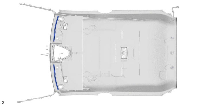
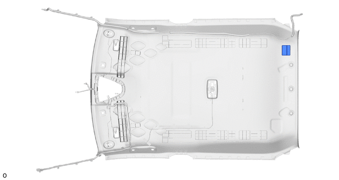
1. REMOVE ROOF HEADLINING FORMING PAD (except Cold Area)
(a) Remove the 2 roof headlining forming pads.
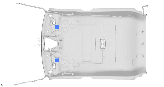
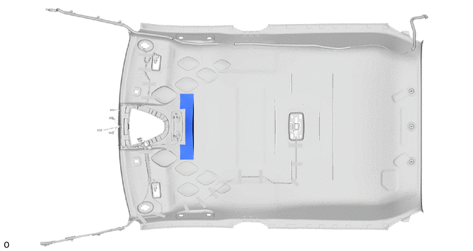
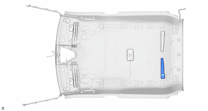
2. REMOVE NO. 1 ROOF SILENCER PAD
(a) Remove the No. 1 roof silencer pad.
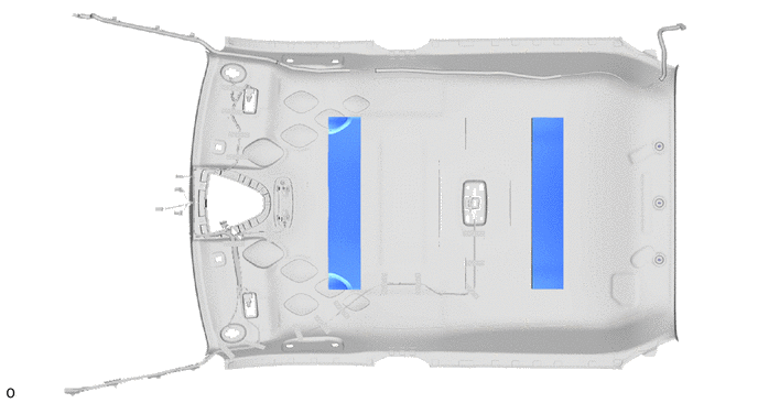
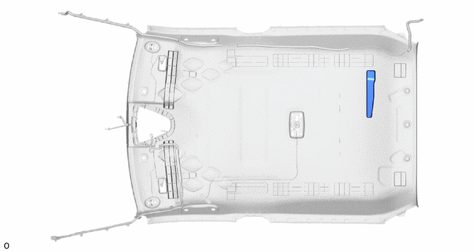
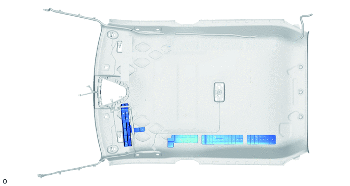
3. REMOVE NO. 2 ROOF SILENCER PAD
(a) Remove the 2 No. 2 roof silencer pads.
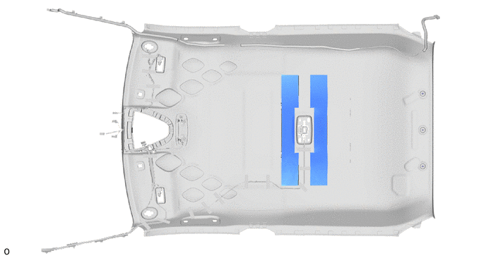
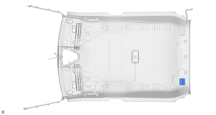
4. REMOVE ROOF SILENCER PAD
(a) Remove the 2 roof silencer pads.
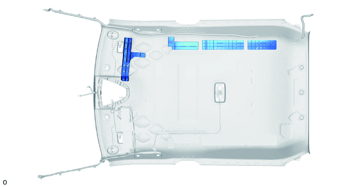
5. REMOVE NO. 3 ROOF SILENCER PAD (for Cold Area)
(a) Peel off the double-sided tape to remove the 2 No. 3 roof silencer pads.
HINT:
Remove any double-sided tape remaining on the roof headlining.
6. REMOVE ROOF HEADLINING PAD LH (for Cold Area)
(a) Remove the roof headlining pad LH.
7. REMOVE ROOF HEADLINING PAD RH (for Cold Area)
(a) Remove the roof headlining pad RH.
8. REMOVE NO. 2 ROOF HEADLINING PAD (for Cold Area)
(a) Remove the No. 2 roof headlining pad.
9. REMOVE ROOF HEADLINING PAD (for Cold Area)
(a) Remove the roof headlining pad.
10. REMOVE SIDE RAIL REAR SPACER LH (for Cold Area)
(a) Remove the 4 side rail rear spacers LH.
11. REMOVE SIDE RAIL REAR SPACER RH (for Cold Area)
(a) Remove the 4 side rail rear spacers RH.
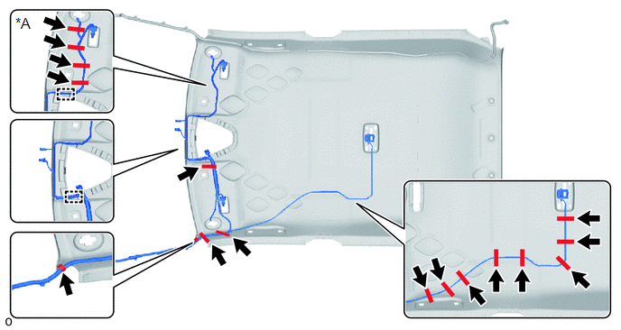
12. REMOVE NO. 1 ROOF WIRE
(a) Disengage each guide.
|
*A |
w/ Vanity Light |
- |
- |
(b) Peel off the pieces of each adhesive tape and remove the No. 1 roof wire.
(c) w/ Vanity Light:
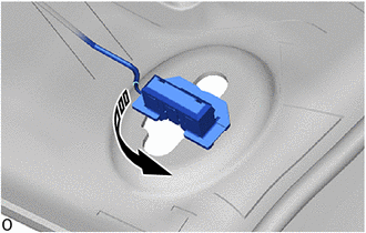
.png) |
Remove in this Direction |
(1) Turn the visor connector approximately 90° counterclockwise and disconnect the visor connectors as shown in the illustration.
HINT:
Use the same procedures for the opposite side.
13. REMOVE NO. 2 ANTENNA CORD SUB-ASSEMBLY
Click here .gif)
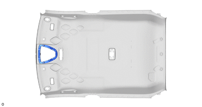
14. REMOVE HEADLINING LIGHT CASE
(a) Remove the headlining light case.
 Components
COMPONENTS
ILLUSTRATION
*A
w/ Package Tray Trim
*B
w/ Tonneau Cover
*1
PACKAGE TRAY TRIM PANEL ASSEMBLY
*2
...
 Reassembly
REASSEMBLY
PROCEDURE
1. INSTALL HEADLINING LIGHT CASE
(a) Align the markings on the roof headlining with the headlining light case
and install it using hot melt glue.
*a
...
Other materials:
Toyota CH-R Service Manual > Can Communication System: Utility
UTILITY
INITIALIZE THE CONNECTION INFORMATION OF A GATEWAY FUNCTION EQUIPPED ECU (BUS
MONITOR ECU)
(a) Connect the Techstream to the DLC3.
(b) Turn the ignition switch to ON.
(c) Turn the Techstream on.
(d) Enter the following menus:
for Body Electrical / Central Gateway / Utility / I ...
Toyota CH-R Service Manual > Headlight Assembly(for Halogen Headlight): Reassembly
REASSEMBLY
CAUTION / NOTICE / HINT
HINT:
Use the same procedure for the RH side and LH side.
The following procedure is for the LH side.
PROCEDURE
1. INSTALL FRONT SIDE MARKER LIGHT BULB (for USA and Canada)
(a) Install the front side marker light bulb to the front side marke ...
Toyota C-HR (AX20) 2023-2026 Owner's Manual
Toyota CH-R Owners Manual
- For safety and security
- Instrument cluster
- Operation of each component
- Driving
- Interior features
- Maintenance and care
- When trouble arises
- Vehicle specifications
- For owners
Toyota CH-R Service Manual
- Introduction
- Maintenance
- Audio / Video
- Cellular Communication
- Navigation / Multi Info Display
- Park Assist / Monitoring
- Brake (front)
- Brake (rear)
- Brake Control / Dynamic Control Systems
- Brake System (other)
- Parking Brake
- Axle And Differential
- Drive Shaft / Propeller Shaft
- K114 Cvt
- 3zr-fae Battery / Charging
- Networking
- Power Distribution
- Power Assist Systems
- Steering Column
- Steering Gear / Linkage
- Alignment / Handling Diagnosis
- Front Suspension
- Rear Suspension
- Tire / Wheel
- Tire Pressure Monitoring
- Door / Hatch
- Exterior Panels / Trim
- Horn
- Lighting (ext)
- Mirror (ext)
- Window / Glass
- Wiper / Washer
- Door Lock
- Heating / Air Conditioning
- Interior Panels / Trim
- Lighting (int)
- Meter / Gauge / Display
- Mirror (int)
- Power Outlets (int)
- Pre-collision
- Seat
- Seat Belt
- Supplemental Restraint Systems
- Theft Deterrent / Keyless Entry

0.0087