Toyota CH-R Service Manual: Inspection
INSPECTION
PROCEDURE
1. INSPECT PRELOAD
|
(a) Secure the steering column assembly in a vise using aluminum plates, cloths and wooden blocks. NOTICE:
|
|
.png)
|
(b) Install 2 service nuts to the steering main shaft. Recommended Service Nut: Thread Diameter 12.0 mm (0.472 in.) Thread Pitch 1.25 mm (0.0492 in.) |
|
.png)
(c) Simultaneously rotate the service nut that was installed first counterclockwise and rotate the service nut that was installed second clockwise to lock them.
NOTICE:
Do not apply excessive torque to the service nuts by using a tool such as an impact wrench.
HINT:
The service nuts are used for turning the steering main shaft during inspection of the steering main shaft rotating torque.
Remove the service nuts after performing this inspection.
|
(d) Using a torque wrench, turn the steering main shaft at a constant rate of approximately 1 revolution every 4 seconds and measure the preload. Preload: 1.2 to 2.4 N*m (13 to 24 kgf*cm, 11 to 21 in.*lbf) If the preload is not as specified, replace the power steering ECU assembly or electric power steering column sub-assembly with a new one. |
|
.png)
(e) Remove the 2 service nuts.
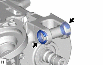
2. INSPECT STEERING COLUMN ASSEMBLY
|
(a) Check that the 2 bushings are securely installed to the steering column assembly. If the bushings are deformed, missing or damaged, replace the electric power steering column sub-assembly with a new one. |
|
 Disassembly
DISASSEMBLY
CAUTION / NOTICE / HINT
NOTICE:
Do not drop the power steering ECU assembly, strike it with tools or
subject it to impacts.
If the power steering ECU assembly is subject ...
 Installation
INSTALLATION
PROCEDURE
1. ALIGN FRONT WHEELS FACING STRAIGHT AHEAD
2. INSTALL STEERING COLUMN ASSEMBLY
NOTICE:
Make sure that the wire harness is not interfering with the steering column assembly ...
Other materials:
Toyota CH-R Service Manual > Vehicle Stability Control System: VSC does not Operate or VSC does not Operate Correctly
DESCRIPTION
When ABS, TRAC or VSC is operating, the skid control ECU (brake actuator assembly)
blinks the slip indicator light to inform the driver that slippage occurred.
When a communication malfunction with the ECM is detected, TRAC and VSC are disabled.
Also, TRAC and VSC are disabled when ...
Toyota CH-R Service Manual > Power Window Control System: Jam Protection Function does not Operate
DESCRIPTION
This symptom may occur for any of the power windows.
The jam protection function operates within a specified range during the manual
up or auto up operation.
CAUTION / NOTICE / HINT
NOTICE:
If a power window regulator motor assembly has been replaced with a
new one, in ...
Toyota C-HR (AX20) 2023-2026 Owner's Manual
Toyota CH-R Owners Manual
- For safety and security
- Instrument cluster
- Operation of each component
- Driving
- Interior features
- Maintenance and care
- When trouble arises
- Vehicle specifications
- For owners
Toyota CH-R Service Manual
- Introduction
- Maintenance
- Audio / Video
- Cellular Communication
- Navigation / Multi Info Display
- Park Assist / Monitoring
- Brake (front)
- Brake (rear)
- Brake Control / Dynamic Control Systems
- Brake System (other)
- Parking Brake
- Axle And Differential
- Drive Shaft / Propeller Shaft
- K114 Cvt
- 3zr-fae Battery / Charging
- Networking
- Power Distribution
- Power Assist Systems
- Steering Column
- Steering Gear / Linkage
- Alignment / Handling Diagnosis
- Front Suspension
- Rear Suspension
- Tire / Wheel
- Tire Pressure Monitoring
- Door / Hatch
- Exterior Panels / Trim
- Horn
- Lighting (ext)
- Mirror (ext)
- Window / Glass
- Wiper / Washer
- Door Lock
- Heating / Air Conditioning
- Interior Panels / Trim
- Lighting (int)
- Meter / Gauge / Display
- Mirror (int)
- Power Outlets (int)
- Pre-collision
- Seat
- Seat Belt
- Supplemental Restraint Systems
- Theft Deterrent / Keyless Entry

0.0099