Toyota CH-R Service Manual: Installation
INSTALLATION
PROCEDURE
1. ALIGN FRONT WHEELS FACING STRAIGHT AHEAD
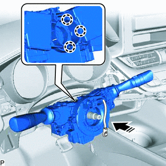
2. INSTALL STEERING COLUMN ASSEMBLY
NOTICE:
Make sure that the wire harness is not interfering with the steering column assembly.
(a) Install the steering column assembly with the bolt and 2 nuts.
Torque:
36 N·m {367 kgf·cm, 27 ft·lbf}
(b) Connect each connector and engage each clamp to the steering column assembly.
(c) Engage the power steering ECU wire harness clamp.
(d) Connect the 2 power steering ECU connectors.
3. CONNECT NO. 2 STEERING INTERMEDIATE SHAFT ASSEMBLY
|
(a) Align the matchmarks on the No. 2 steering intermediate shaft assembly and steering column assembly. |
|
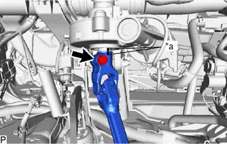
(b) Connect the No. 2 steering intermediate shaft assembly to the steering column assembly.
(c) Install the bolt.
Torque:
64 N·m {653 kgf·cm, 47 ft·lbf}
4. INSTALL NO. 2 STEERING INTERMEDIATE SHAFT ASSEMBLY
|
(a) Align the matchmarks on the No. 2 steering intermediate shaft assembly and steering gear assembly. |
|
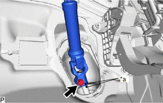
(b) Install the No. 2 steering intermediate shaft assembly to the steering gear assembly.
(c) Install the bolt.
Torque:
64 N·m {653 kgf·cm, 47 ft·lbf}
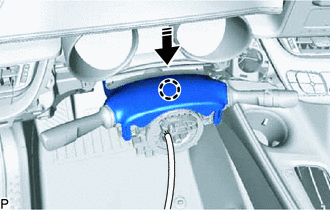
5. INSTALL COLUMN HOLE COVER SILENCER SHEET
|
(a) Engage the 2 claws to install the column hole cover silencer sheet. |
|
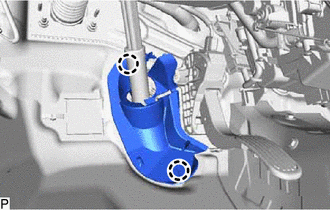
(b) Engage the claw to close the column hole cover silencer sheet.
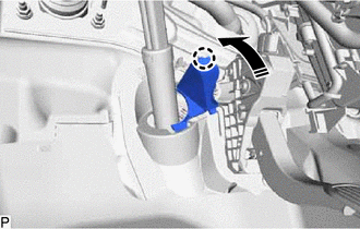
.png) |
Engage in this direction |
6. INSTALL STOP LIGHT SWITCH ASSEMBLY
Click here
.gif)
7. INSTALL NO. 1 AIR DUCT
(a) Engage the 3 claws to install a new No. 1 air duct.
(b) Install the 2 bolts.
8. INSTALL CONSOLE BOX INSERT
Click here
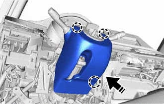
9. INSTALL TURN SIGNAL SWITCH ASSEMBLY WITH SPIRAL CABLE SUB-ASSEMBLY
NOTICE:
- Do not replace the spiral cable with sensor sub-assembly with the battery connected and the ignition switch ON.
- Do not rotate the spiral cable with sensor sub-assembly without the steering wheel assembly installed with the battery connected and the ignition switch ON.
- Ensure that the steering wheel assembly is installed and aligned straight when inspecting the steering sensor.
(a) Engage the 3 claws to install the turn signal switch assembly with spiral cable sub-assembly to the steering column assembly as shown in the illustration.
|
|
Install in this Direction |
(b) Connect each connector to the turn signal switch assembly with spiral cable sub-assembly.
10. INSTALL UPPER STEERING COLUMN COVER
(a) Engage the 2 claws and 4 clips to connect the upper steering column cover.
|
|
Install in this Direction |
(b) Engage the claw to install the upper steering column cover as shown in the illustration.
11. INSTALL LOWER STEERING COLUMN COVER SUB-ASSEMBLY
NOTICE:
If the lower steering column cover sub-assembly is installed in the incorrect order, the parts may break.
|
|
Install in this Direction |
(a) Engage the 3 claws to install the lower steering column cover sub-assembly as shown in the illustration.
(b) Engage the 4 claws.
(c) Install the 2 screws.
12. INSTALL LOWER NO. 1 INSTRUMENT PANEL AIRBAG ASSEMBLY
Click here
13. ALIGN FRONT WHEELS FACING STRAIGHT AHEAD
14. INSPECT AND ADJUST SPIRAL CABLE WITH SENSOR SUB-ASSEMBLY
Click here
15. INSTALL STEERING WHEEL ASSEMBLY
Click here
16. CHECK STEERING WHEEL CENTER POINT
17. INSTALL HORN BUTTON ASSEMBLY
Click here
18. TORQUE SENSOR ZERO POINT CALIBRATION
Click here
 Inspection
INSPECTION
PROCEDURE
1. INSPECT PRELOAD
(a) Secure the steering column assembly in a vise using aluminum plates,
cloths and wooden blocks.
NOTICE:
Do not overtight ...
 Reassembly
REASSEMBLY
CAUTION / NOTICE / HINT
NOTICE:
Do not drop the power steering ECU assembly, strike it with tools or
subject it to impacts.
If the power steering ECU assembly is subjecte ...
Other materials:
Toyota CH-R Service Manual > Back Door Outside Garnish: Disassembly
DISASSEMBLY
PROCEDURE
1. REMOVE NO. 2 BACK DOOR OUTSIDE GARNISH
(a) Remove the 7 No. 1 outside moulding retainers and No. 2 back door outside
garnish as shown in the illustration.
Remove in this Direction
2. REMOVE BACK DOOR GARNISH SIDE PROTECTOR LH
...
Toyota CH-R Service Manual > Compressor(for Valeo Made): Removal
REMOVAL
PROCEDURE
1. RECOVER REFRIGERANT FROM REFRIGERATION SYSTEM (for HFC-134a(R134a))
Click here
2. RECOVER REFRIGERANT FROM REFRIGERATION SYSTEM (for HFO-1234yf(R1234yf))
Click here
3. REMOVE NO. 1 ENGINE UNDER COVER
Click here
4. REMOVE FAN AND GENERATOR V BELT
Click here
...
Toyota C-HR (AX20) 2023-2026 Owner's Manual
Toyota CH-R Owners Manual
- For safety and security
- Instrument cluster
- Operation of each component
- Driving
- Interior features
- Maintenance and care
- When trouble arises
- Vehicle specifications
- For owners
Toyota CH-R Service Manual
- Introduction
- Maintenance
- Audio / Video
- Cellular Communication
- Navigation / Multi Info Display
- Park Assist / Monitoring
- Brake (front)
- Brake (rear)
- Brake Control / Dynamic Control Systems
- Brake System (other)
- Parking Brake
- Axle And Differential
- Drive Shaft / Propeller Shaft
- K114 Cvt
- 3zr-fae Battery / Charging
- Networking
- Power Distribution
- Power Assist Systems
- Steering Column
- Steering Gear / Linkage
- Alignment / Handling Diagnosis
- Front Suspension
- Rear Suspension
- Tire / Wheel
- Tire Pressure Monitoring
- Door / Hatch
- Exterior Panels / Trim
- Horn
- Lighting (ext)
- Mirror (ext)
- Window / Glass
- Wiper / Washer
- Door Lock
- Heating / Air Conditioning
- Interior Panels / Trim
- Lighting (int)
- Meter / Gauge / Display
- Mirror (int)
- Power Outlets (int)
- Pre-collision
- Seat
- Seat Belt
- Supplemental Restraint Systems
- Theft Deterrent / Keyless Entry

0.0073