Toyota CH-R Service Manual: Brake Pedal Load Sensing Switch OFF Stuck Malfunction (C1430,C1431)
DESCRIPTION
The brake pedal load sensing switch turns on when the brake pedal is depressed with a force exceeding a predetermined level.
The skid control ECU uses this circuit to detect if the brake pedal is depressed or not.
|
DTC No. |
Detection Item |
DTC Detection Condition |
Trouble Area |
|---|---|---|---|
|
C1430 |
Brake Pedal Load Sensing Switch OFF Stuck Malfunction |
Either of the following is detected:
|
|
|
C1431 |
Brake Pedal Load Sensing Switch ON Stuck Malfunction |
Either of the following is detected:
|
|
|
Vehicle Condition |
|||
|---|---|---|---|
|
Pattern 1 |
Pattern 2 |
||
|
Diagnosis Condition |
- |
- |
- |
|
Malfunction Status |
With the stop light switch on, the brake pedal load sensing switch off, and the master cylinder pressure more than 6 MPa (61.2 kgf/ cm2, 870 psi), the vehicle acceleration rate is less than -4 m/s2. |
○ |
- |
|
With the stop light switch on, the brake pedal load sensing switch off, and the master cylinder pressure more than 6 MPa (61.2 kgf/ cm2, 870 psi), the vehicle speed is 0 km/h (0 mph). |
- |
○ |
|
|
Detection Time |
1 second or more |
5 seconds or more |
|
|
Number of Trips |
1 trip |
1 trip |
|
HINT:
DTC will be output when conditions for either of the patterns in the table above are met.
DTC Detection Conditions: C1431|
Vehicle Condition |
|||
|---|---|---|---|
|
Pattern 1 |
Pattern 2 |
||
|
Diagnosis Condition |
- |
- |
- |
|
Malfunction Status |
With the stop light switch off, the brake pedal load sensing switch on, and the master cylinder pressure less than 0.7 MPa (7.13 kgf/cm2, 101 psi), the vehicle acceleration rate is more than -0.8 m/s2. (Only when the engine is running and booster malfunctions are not detected.) |
○ |
- |
|
Condition which the brake pedal load sensing switch remains on while the vehicle speed increases from 0 km/h (0 mph) to 30 km/h (19 mph) occurs 5 times in succession. |
- |
○ |
|
|
Detection Time |
10 seconds or more |
- |
|
|
Number of Trips |
1 trip |
1 trip |
|
HINT:
DTC will be output when conditions for either of the patterns in the table above are met.
WIRING DIAGRAM
Refer to DTC C1429.
Click here
.gif)
CAUTION / NOTICE / HINT
HINT:
When C1249, C1425 and/or C1426 is output together with C1430 and/or C1431, inspect
and repair the trouble areas indicated by C1249, C1425 and/or C1426 first (Click
here
), Click here
), and/or Click here
)).
PROCEDURE
|
1. |
READ VALUE USING TECHSTREAM (STOP LIGHT SWITCH ASSEMBLY AND BRAKE PEDAL LOAD SENSING SWITCH) |
(a) Connect the Techstream to the DLC3.
(b) Turn the ignition switch to ON.
(c) Select the Data List using the Techstream.
Click here
|
Tester Display |
Measurement Item |
Range |
Normal Condition |
Diagnostic Note |
|---|---|---|---|---|
|
Stop Light SW |
Stop light switch |
ON or OFF |
ON: Brake pedal depressed OFF: Brake pedal released |
- |
|
Brake Pedal Load Sensing SW |
Brake pedal load sensing switch |
ON or OFF |
ON: Brake pedal depressed beyond as pecified point OFF: Brake pedal not depressed beyond as pecified point |
- |
(d) Check that the stop light switch display and brake pedal load sensing switch display observed on the Techstream change according to brake pedal operation.
OK:
The Techstream displays ON or OFF according to brake pedal operation.
(e) Slowly depress the brake pedal, and check when the stop light switch and brake pedal load sensing switch turn on.
OK:
First the stop light switch turns on, and then the brake pedal load sensing switch turns on.
|
Result |
Proceed to |
|---|---|
|
OK |
A |
|
NG (Turning on of the brake pedal load sensing switch is not confirmed.) |
B |
|
NG (The brake pedal load sensing switch turns on first.) |
C |
| B | .gif) |
GO TO STEP 3 |
| C | |
GO TO STEP 5 |
|
.gif)
|
2. |
RECONFIRM DTC |
(a) Turn the ignition switch off.
(b) Clear the DTCs.
Click here
(c) Turn the ignition switch off.
(d) Start the engine.
(e) Perform a road test.
(f) Check if the same DTC is output.
Click here
|
Result |
Proceed to |
|---|---|
|
DTCs C1430 and C1431 are not output. |
A |
|
DTCs C1430 and C1431 are output. |
B |
| A | |
END |
| B | |
REPLACE BRAKE ACTUATOR ASSEMBLY |
|
3. |
INSPECT BRAKE PEDAL LOAD SENSING SWITCH |
(a) Turn the ignition switch off.
(b) Make sure that there is no looseness at the locking part and the connecting part of the connector.
(c) Disconnect the A63 brake pedal load sensing switch connector.
NOTICE:
- Do not remove the brake pedal load sensing switch from the brake pedal support assembly.
- When there is a malfunction in the brake pedal load sensing switch, replace the brake pedal support assembly.
|
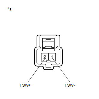
*a |
Component without harness connected (Brake Pedal Load Sensing Switch (Brake Pedal Support Assembly)) |
(d) Measure the resistance according to the value(s) in the table below.
Standard Resistance:
|
Tester Connection |
Condition |
Specified Condition |
|---|---|---|
|
2 (FSW+) - 1 (FSW-) |
Switch OFF (Brake pedal depressed) |
950 to 1050 Ω |
|
2 (FSW+) - 1 (FSW-) |
Switch ON (Brake pedal released) |
203 to 223 Ω |
| NG | |
REPLACE BRAKE PEDAL SUPPORT ASSEMBLY |
|
|
4. |
CHECK HARNESS AND CONNECTOR (BRAKE ACTUATOR ASSEMBLY - BRAKE PEDAL LOAD SENSING SWITCH) |
(a) Make sure that there is no looseness at the locking part and the connecting part of the connector.
(b) Disconnect the A42 skid control ECU (brake actuator assembly) connector.
(c) Measure the resistance according to the value(s) in the table below.
Standard Resistance:
|
Tester Connection |
Condition |
Specified Condition |
|---|---|---|
|
A42-17 (FSW+) -A63-2 (FSW+) |
Always |
Below 1 Ω |
|
A42-17 (FSW+) - Body ground |
Always |
10 kΩ or higher |
|
A63-2 (FSW+) -Body ground |
Always |
10 kΩ or higher |
|
A63-1 (FSW-) -Body ground |
Always |
Below 1 Ω |
| OK | |
REPLACE BRAKE ACTUATOR ASSEMBLY |
| NG | |
REPAIR OR REPLACE HARNESS OR CONNECTOR |
|
5. |
CHECK BRAKE PEDAL AND STOP LIGHT SWITCH ASSEMBLY INSTALLATION |
(a) Turn the ignition switch off.
(b) Check the brake pedal height.
Click here
(c) Check the stop light switch assembly installation.
Click here
OK:
The brake pedal height and stop light switch assembly installation are normal.
| OK | |
REPLACE BRAKE PEDAL SUPPORT ASSEMBLY |
| NG | |
ADJUST BRAKE PEDAL OR STOP LIGHT SWITCH ASSEMBLY |
 Open or Short in Brake Pedal Load Sensing Switch (C1429)
DESCRIPTION
The brake pedal load sensing switch turns on when the brake pedal is depressed
with a force exceeding a predetermined level.
The skid control ECU uses this circuit to detect if the bra ...
 Steering Angle Sensor Power Source Voltage Malfunction (C1432)
DESCRIPTION
This DTC is stored when the skid control ECU (brake actuator assembly) receives
a +B line open signal from the steering angle sensor.
DTC No.
Detection Item
...
Other materials:
Toyota CH-R Service Manual > Audio And Visual System(for Radio Receiver Type): Radio Receiver Power Source Circuit
DESCRIPTION
This is the power source circuit to operate the radio receiver assembly.
WIRING DIAGRAM
CAUTION / NOTICE / HINT
NOTICE:
Inspect the fuses for circuits related to this system before performing the following
procedure.
PROCEDURE
1.
CHECK HARNESS AND CONNEC ...
Toyota CH-R Service Manual > Automatic Headlight Beam Level Control System: Height Control Sensor Malfunction (B2416,B241A)
DESCRIPTION
This DTC is stored when the headlight ECU sub-assembly LH detects a malfunction
in the rear height control sensor sub-assembly LH power source circuit or rear height
control sensor sub-assembly LH circuit. The headlight ECU sub-assembly LH stores
DTC B2416 and B241A.
D ...
Toyota C-HR (AX20) 2023-2026 Owner's Manual
Toyota CH-R Owners Manual
- For safety and security
- Instrument cluster
- Operation of each component
- Driving
- Interior features
- Maintenance and care
- When trouble arises
- Vehicle specifications
- For owners
Toyota CH-R Service Manual
- Introduction
- Maintenance
- Audio / Video
- Cellular Communication
- Navigation / Multi Info Display
- Park Assist / Monitoring
- Brake (front)
- Brake (rear)
- Brake Control / Dynamic Control Systems
- Brake System (other)
- Parking Brake
- Axle And Differential
- Drive Shaft / Propeller Shaft
- K114 Cvt
- 3zr-fae Battery / Charging
- Networking
- Power Distribution
- Power Assist Systems
- Steering Column
- Steering Gear / Linkage
- Alignment / Handling Diagnosis
- Front Suspension
- Rear Suspension
- Tire / Wheel
- Tire Pressure Monitoring
- Door / Hatch
- Exterior Panels / Trim
- Horn
- Lighting (ext)
- Mirror (ext)
- Window / Glass
- Wiper / Washer
- Door Lock
- Heating / Air Conditioning
- Interior Panels / Trim
- Lighting (int)
- Meter / Gauge / Display
- Mirror (int)
- Power Outlets (int)
- Pre-collision
- Seat
- Seat Belt
- Supplemental Restraint Systems
- Theft Deterrent / Keyless Entry

0.0149