Toyota CH-R Service Manual: Height Control Sensor Malfunction (B2416,B241A)
DESCRIPTION
This DTC is stored when the headlight ECU sub-assembly LH detects a malfunction in the rear height control sensor sub-assembly LH power source circuit or rear height control sensor sub-assembly LH circuit. The headlight ECU sub-assembly LH stores DTC B2416 and B241A.
|
DTC No. |
Detection Item |
DTC Detection Condition |
Trouble Area |
Note |
|---|---|---|---|---|
|
B2416 |
Height Control Sensor Malfunction |
Any of the following conditions is met:
|
|
- |
|
B241A |
Rear Height Control Sensor |
Any of the following conditions is met:
|
|
- |
|
Vehicle Condition |
||||
|---|---|---|---|---|
|
Pattern 1 |
Pattern 2 |
Pattern 3 |
||
|
Diagnosis Condition |
Ignition switch ON |
○ |
○ |
○ |
|
Malfunction Status |
Malfunction in rear height control sensor sub-assembly LH |
○ |
- |
- |
|
Open in rear height control sensor sub-assembly LH power source circuit |
- |
○ |
- |
|
|
Short in rear height control sensor sub-assembly LH power source circuit |
- |
- |
○ |
|
|
Detection Time |
- |
- |
- |
|
|
Number of Trips |
1 trip |
1 trip |
1 trip |
|
HINT:
DTC will be output when conditions for either of the patterns in the table above are met.
WIRING DIAGRAM
CAUTION / NOTICE / HINT
NOTICE:
- Before performing this inspection, check that the rear height control sensor sub-assembly LH is installed correctly.
- If the headlight ECU sub-assembly LH has been replaced, it is necessary
to synchronize the vehicle information and initialize the headlight ECU
sub-assembly LH.
Click here
.gif)
- If any of the following are performed, it is necessary to initialize
the headlight ECU sub-assembly LH.
Click here
- Replacement of the rear height control sensor sub-assembly LH
- Removal/installation of the rear height control sensor sub-assembly LH
- Work that changes the vehicle height such as replacement of suspension components
PROCEDURE
|
1. |
CLEAR DTC |
(a) Clear the DTCs.
Click here
|
.gif)
|
2. |
CHECK FOR DTC |
(a) Check for DTCs.
Click here
OK:
DTC B2416 or B241A are not output.
| OK | .gif) |
USE SIMULATION METHOD TO CHECK
|
|
|
3. |
READ VALUE USING TECHSTREAM |
(a) Connect the Techstream to the DLC3.
(b) Turn the ignition switch to ON.
(c) Turn the Techstream on.
(d) Enter the following menus: Body Electrical / HL AutoLeveling / Data List.
(e) Read the Data List according to the display on the Techstream.
Body Electrical > HL AutoLeveling > Data List|
Tester Display |
Measurement Item |
Range |
Normal Condition |
Diagnostic Note |
|---|---|---|---|---|
|
Height Sens Pw Supply Val |
Rear height control sensor sub-assembly LH power supply value |
0 to 5.00 V |
4.61 to 5.00 V |
- |
|
Rr Height Sens Signal Val |
Rear height control sensor sub-assembly LH signal value |
0 to 5.00 V |
0.50 to 4.50 V |
Value changes according to vehicle height |
|
Tester Display |
|---|
|
Height Sens Pw Supply Val |
|
Rr Height Sens Signal Val |
OK:
Normal condition listed above is displayed.
| OK | |
REPLACE HEADLIGHT ECU SUB-ASSEMBLY LH |
|
|
4. |
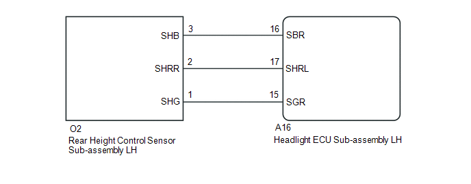
CHECK HARNESS AND CONNECTOR (HEADLIGHT ECU SUB-ASSEMBLY LH - REAR HEIGHT CONTROL SENSOR SUB-ASSEMBLY LH) |
(a) Disconnect the A16 headlight ECU sub-assembly LH connector.
(b) Disconnect the O2 rear height control sensor sub-assembly LH connector.
(c) Measure the resistance according to the value(s) in the table below.
Standard Resistance:
|
Tester Connection |
Condition |
Specified Condition |
|---|---|---|
|
A16-16 (SBR) - O2-3 (SHB) |
Always |
Below 1 Ω |
|
A16-17 (SHRL) - O2-2 (SHRR) |
Always |
Below 1 Ω |
|
A16-15 (SGR) - O2-1 (SHG) |
Always |
Below 1 Ω |
|
A16-16 (SBR) or O2-3 (SHB) - Body ground |
Always |
10 kΩ or higher |
|
A16-17 (SHRL) or O2-2 (SHRR) - Body ground |
Always |
10 kΩ or higher |
|
A16-15 (SGR) or O2-1 (SHG) - Body ground |
Always |
10 kΩ or higher |
| NG | |
REPAIR OR REPLACE HARNESS OR CONNECTOR |
|
|
5. |
INSPECT REAR HEIGHT CONTROL SENSOR SUB-ASSEMBLY LH |
(a) Remove the rear height control sensor sub-assembly LH.
Click here
(b) Inspect the rear height control sensor sub-assembly LH.
Click here
OK:
Rear height control sensor sub-assembly LH is normal.
| OK | |
REPLACE HEADLIGHT ECU SUB-ASSEMBLY LH |
| NG | |
REPLACE REAR HEIGHT CONTROL SENSOR SUB-ASSEMBLY LH |
 Vehicle Speed Sensor Malfunction (B2415)
DESCRIPTION
The headlight ECU sub-assembly LH receives signals indicating the vehicle speed
signal from the brake actuator assembly (skid control ECU) using CAN communication.
The headlight ECU s ...
 Automatic High Beam Main Switch
Components
COMPONENTS
ILLUSTRATION
*1
AUTO HIGH BEAM SWITCH
*2
INSTRUMENT CLUSTER FINISH PANEL SUB-ASSEMBLY
Removal
REMOVAL
PROCEDURE
...
Other materials:
Toyota CH-R Service Manual > Lighting System: Door Courtesy Switch Circuit
DESCRIPTION
The main body ECU (multiplex network body ECU) detects the condition of the door
courtesy light switch assembly.
WIRING DIAGRAM
CAUTION / NOTICE / HINT
NOTICE:
Before replacing the main body ECU (multiplex network body ECU), refer to Registration*1.
Click here
*1: w/ ...
Toyota CH-R Service Manual > Tire Pressure Warning Valve: Removal
REMOVAL
CAUTION / NOTICE / HINT
The necessary procedures (adjustment, calibration, initialization or registration)
that must be performed after parts are removed and installed, or replaced during
tire pressure warning valve and transmitter removal/installation are shown below.
Repl ...
Toyota C-HR (AX20) 2023-2026 Owner's Manual
Toyota CH-R Owners Manual
- For safety and security
- Instrument cluster
- Operation of each component
- Driving
- Interior features
- Maintenance and care
- When trouble arises
- Vehicle specifications
- For owners
Toyota CH-R Service Manual
- Introduction
- Maintenance
- Audio / Video
- Cellular Communication
- Navigation / Multi Info Display
- Park Assist / Monitoring
- Brake (front)
- Brake (rear)
- Brake Control / Dynamic Control Systems
- Brake System (other)
- Parking Brake
- Axle And Differential
- Drive Shaft / Propeller Shaft
- K114 Cvt
- 3zr-fae Battery / Charging
- Networking
- Power Distribution
- Power Assist Systems
- Steering Column
- Steering Gear / Linkage
- Alignment / Handling Diagnosis
- Front Suspension
- Rear Suspension
- Tire / Wheel
- Tire Pressure Monitoring
- Door / Hatch
- Exterior Panels / Trim
- Horn
- Lighting (ext)
- Mirror (ext)
- Window / Glass
- Wiper / Washer
- Door Lock
- Heating / Air Conditioning
- Interior Panels / Trim
- Lighting (int)
- Meter / Gauge / Display
- Mirror (int)
- Power Outlets (int)
- Pre-collision
- Seat
- Seat Belt
- Supplemental Restraint Systems
- Theft Deterrent / Keyless Entry

0.0102