Toyota CH-R Service Manual: Vehicle Speed Sensor Malfunction (B2415)
DESCRIPTION
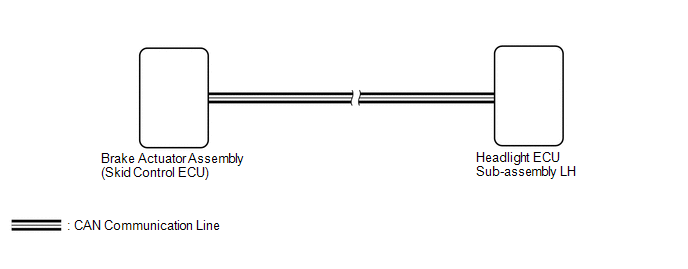
The headlight ECU sub-assembly LH receives signals indicating the vehicle speed signal from the brake actuator assembly (skid control ECU) using CAN communication. The headlight ECU sub-assembly LH stores DTC B2415.
|
DTC No. |
Detection Item |
DTC Detection Condition |
Trouble Area |
Note |
|---|---|---|---|---|
|
B2415 |
Vehicle Speed Sensor Malfunction |
Malfunction in vehicle speed signal |
|
- |
WIRING DIAGRAM
CAUTION / NOTICE / HINT
NOTICE:
- Confirm that there are no CAN communication system malfunctions before
performing the following inspection.
Click here
.gif)
- If the headlight ECU sub-assembly LH has been replaced, it is necessary
to synchronize the vehicle information and initialize the headlight ECU
sub-assembly LH.
Click here
PROCEDURE
|
1. |
CLEAR DTC |
(a) Clear the DTCs.
Click here
|
.gif)
|
2. |
CHECK FOR DTC |
(a) Turn the ignition switch to ON.
(b) Check for DTCs.
Click here
OK:
DTC B2415 is not output.
| OK | .gif) |
USE SIMULATION METHOD TO CHECK
|
|
|
3. |
CHECK FOR DTC (VEHICLE STABILITY CONTROL SYSTEM) |
(a) Check for DTCs.
Click here
OK:
Vehicle stability control system DTCs are not output.
| OK | |
REPLACE HEADLIGHT ECU SUB-ASSEMBLY LH |
| NG | |
GO TO VEHICLE STABILITY CONTROL SYSTEM |
 Headlight Beam Level Control Motor LH Malfunction (B2417,B2418)
DESCRIPTION
The headlight unit (headlight leveling motor) receives a signal from the headlight
control ECU sub-assembly to operate. The headlight control ECU sub-assembly receives
a signal indica ...
 Height Control Sensor Malfunction (B2416,B241A)
DESCRIPTION
This DTC is stored when the headlight ECU sub-assembly LH detects a malfunction
in the rear height control sensor sub-assembly LH power source circuit or rear height
control sensor su ...
Other materials:
Toyota CH-R Service Manual > Smart Key System(for Entry Function): Open in Driver Side Electrical Antenna Circuit (B27A1)
DESCRIPTION
The certification ECU (smart key ECU assembly) generates a request signal and
transmits the signal to the front door outside handle assembly LH (electrical key
antenna) at intervals of 0.25 seconds. For the front door outside handle assembly
LH (electrical key antenna) to detect w ...
Toyota CH-R Service Manual > Navigation System: Speed Signal Malfunction (B15C2)
DESCRIPTION
The navigation ECU receives a vehicle speed signal from the combination meter
assembly and information from the navigation antenna assembly, and then adjusts
the vehicle position on the map.
The navigation ECU stores this DTC when the difference between the speed information
that ...
Toyota C-HR (AX20) 2023-2026 Owner's Manual
Toyota CH-R Owners Manual
- For safety and security
- Instrument cluster
- Operation of each component
- Driving
- Interior features
- Maintenance and care
- When trouble arises
- Vehicle specifications
- For owners
Toyota CH-R Service Manual
- Introduction
- Maintenance
- Audio / Video
- Cellular Communication
- Navigation / Multi Info Display
- Park Assist / Monitoring
- Brake (front)
- Brake (rear)
- Brake Control / Dynamic Control Systems
- Brake System (other)
- Parking Brake
- Axle And Differential
- Drive Shaft / Propeller Shaft
- K114 Cvt
- 3zr-fae Battery / Charging
- Networking
- Power Distribution
- Power Assist Systems
- Steering Column
- Steering Gear / Linkage
- Alignment / Handling Diagnosis
- Front Suspension
- Rear Suspension
- Tire / Wheel
- Tire Pressure Monitoring
- Door / Hatch
- Exterior Panels / Trim
- Horn
- Lighting (ext)
- Mirror (ext)
- Window / Glass
- Wiper / Washer
- Door Lock
- Heating / Air Conditioning
- Interior Panels / Trim
- Lighting (int)
- Meter / Gauge / Display
- Mirror (int)
- Power Outlets (int)
- Pre-collision
- Seat
- Seat Belt
- Supplemental Restraint Systems
- Theft Deterrent / Keyless Entry

0.008