Toyota CH-R Service Manual: Automatic High Beam Main Switch
Components
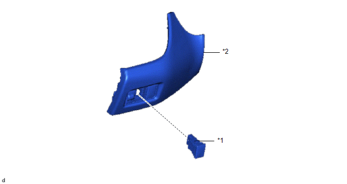
COMPONENTS
ILLUSTRATION
|
*1 |
AUTO HIGH BEAM SWITCH |
*2 |
INSTRUMENT CLUSTER FINISH PANEL SUB-ASSEMBLY |
Removal
REMOVAL
PROCEDURE
1. REMOVE INSTRUMENT CLUSTER FINISH PANEL SUB-ASSEMBLY
Click here
.gif)
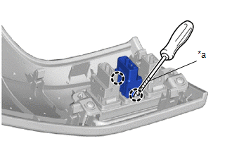
2. REMOVE AUTO HIGH BEAM SWITCH
|
(a) Using a screwdriver with its tip wrapped in protective tape, disengage the claws to remove the auto high beam switch. |
|
Inspection
INSPECTION
PROCEDURE
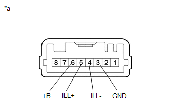
1. INSPECT AUTO HIGH BEAM SWITCH
(a) Check the resistance.
|
(1) Measure the resistance according to the value(s) in the table below. Standard Resistance:
If the result is not as specified, replace the auto high beam switch. |
|
(b) Check the illumination.
(1) Apply battery voltage to the auto high beam switch and check that it illuminates.
OK:
|
Condition |
Specified Condition |
|---|---|
|
Battery positive (+) → Terminal 5 (ILL+) Battery negative (-) → Terminal 4 (ILL-) |
Illuminates |
If the result is not as specified, replace the auto high beam switch.
Installation
INSTALLATION
PROCEDURE
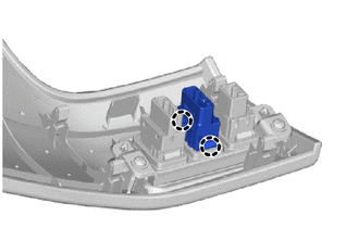
1. INSTALL AUTO HIGH BEAM SWITCH
|
(a) Engage the claws to install the auto high beam switch as shown in the illustration. |
|
2. INSTALL INSTRUMENT CLUSTER FINISH PANEL SUB-ASSEMBLY
Click here
.gif)
 Height Control Sensor Malfunction (B2416,B241A)
DESCRIPTION
This DTC is stored when the headlight ECU sub-assembly LH detects a malfunction
in the rear height control sensor sub-assembly LH power source circuit or rear height
control sensor su ...

Other materials:
Toyota CH-R Service Manual > Headlight Assembly(for Halogen Headlight): Reassembly
REASSEMBLY
CAUTION / NOTICE / HINT
HINT:
Use the same procedure for the RH side and LH side.
The following procedure is for the LH side.
PROCEDURE
1. INSTALL FRONT SIDE MARKER LIGHT BULB (for USA and Canada)
(a) Install the front side marker light bulb to the front side marke ...
Toyota CH-R Service Manual > Power Window Control System: Rear Power Window RH Auto Up / Down Function does not Operate with Rear Power
Window Switch RH
DESCRIPTION
If the manual up and down functions operate normally but the auto up and down
functions do not, the power window control system may be in fail-safe mode.
If power window initialization has not been performed, the auto up and down functions
will not operate.
Click here
WIRING ...
Toyota C-HR (AX20) 2023-2026 Owner's Manual
Toyota CH-R Owners Manual
- For safety and security
- Instrument cluster
- Operation of each component
- Driving
- Interior features
- Maintenance and care
- When trouble arises
- Vehicle specifications
- For owners
Toyota CH-R Service Manual
- Introduction
- Maintenance
- Audio / Video
- Cellular Communication
- Navigation / Multi Info Display
- Park Assist / Monitoring
- Brake (front)
- Brake (rear)
- Brake Control / Dynamic Control Systems
- Brake System (other)
- Parking Brake
- Axle And Differential
- Drive Shaft / Propeller Shaft
- K114 Cvt
- 3zr-fae Battery / Charging
- Networking
- Power Distribution
- Power Assist Systems
- Steering Column
- Steering Gear / Linkage
- Alignment / Handling Diagnosis
- Front Suspension
- Rear Suspension
- Tire / Wheel
- Tire Pressure Monitoring
- Door / Hatch
- Exterior Panels / Trim
- Horn
- Lighting (ext)
- Mirror (ext)
- Window / Glass
- Wiper / Washer
- Door Lock
- Heating / Air Conditioning
- Interior Panels / Trim
- Lighting (int)
- Meter / Gauge / Display
- Mirror (int)
- Power Outlets (int)
- Pre-collision
- Seat
- Seat Belt
- Supplemental Restraint Systems
- Theft Deterrent / Keyless Entry

0.0074