Toyota CH-R Service Manual: Terminals Of Ecu
TERMINALS OF ECU
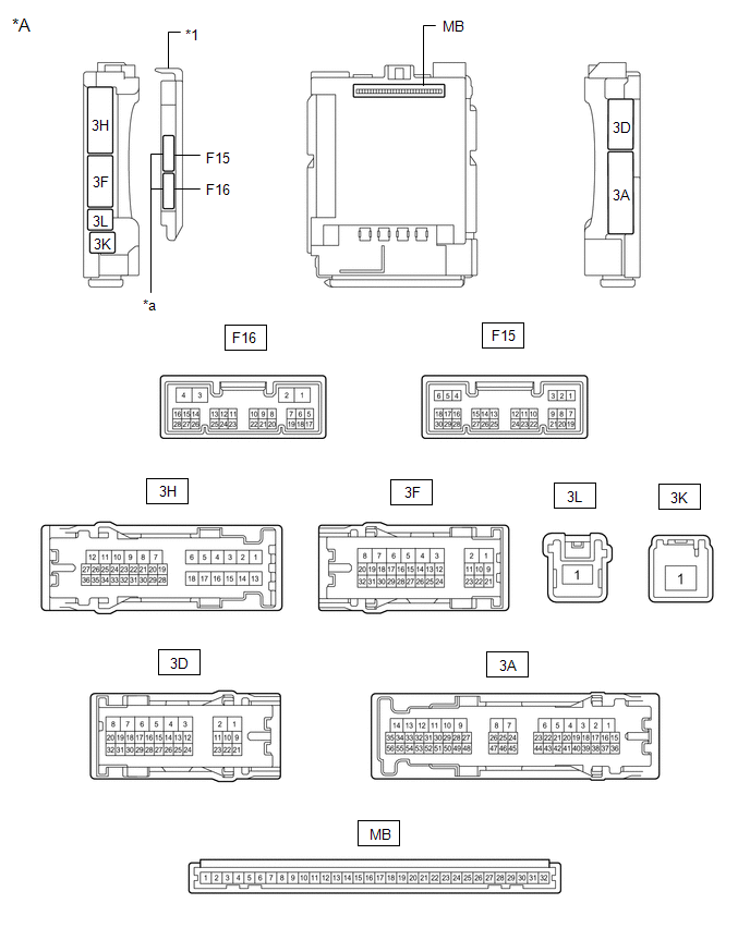
CHECK MAIN BODY ECU (MULTIPLEX NETWORK BODY ECU) AND INSTRUMENT PANEL JUNCTION BLOCK ASSEMBLY
|
*A |
Main Body ECU (Multiplex Network Body ECU) with 2 Connectors |
- |
- |
|
*1 |
Main Body ECU (Multiplex Network Body ECU) |
- |
- |
|
*a |
2 Connectors |
- |
- |
|
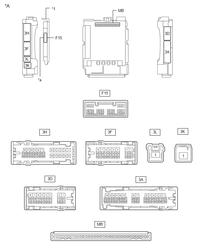
*A |
Main Body ECU (Multiplex Network Body ECU) with 1 Connector |
- |
- |
|
*1 |
Main Body ECU (Multiplex Network Body ECU) |
- |
- |
|
*a |
1 Connector |
- |
- |
(a) Remove the main body ECU (multiplex network body ECU) from the instrument panel junction block assembly.
Click here
.gif)
(b) Reconnect the instrument panel junction block assembly connectors.
(c) Measure the resistance and voltage according to the value(s) in the table below.
HINT:
Measure the values on the wire harness side with the connector disconnected.
|
Terminal No. (Symbol) |
Wiring Color |
Terminal Description |
Condition |
Specified Condition |
|---|---|---|---|---|
|
MB-11 (GND1) - Body ground |
- |
Ground |
Always |
Below 1 Ω |
|
MB-31 (BECU) - Body ground |
- |
Battery power supply |
Always |
11 to 14 V |
|
MB-30 (ACC) - Body ground |
- |
ACC power supply |
Ignition switch ACC |
11 to 14 V |
|
MB-30 (ACC) - Body ground |
- |
ACC power supply |
Ignition switch off |
Below 1 V |
|
MB-32 (IG) - Body ground |
- |
IG power supply |
Ignition switch ON |
11 to 14 V |
|
MB-32 (IG) - Body ground |
- |
IG power supply |
Ignition switch off |
Below 1 V |
(d) Install the main body ECU (multiplex network body ECU) to instrument panel junction block assembly.
Click here
(e) Measure the voltage and check for pulses according to the value(s) in the table below.
|
Terminal No. (Symbol) |
Wiring Color |
Terminal Description |
Condition |
Specified Condition |
|---|---|---|---|---|
|
F15-6 (FLCY) - Body ground |
R - Body ground |
Front door courtesy light switch (for LH) input |
Front door LH open |
Below 1 V |
|
F15-6 (FLCY) - Body ground |
R - Body ground |
Front door courtesy light switch (for LH) input |
Front door LH closed |
Pulse generation |
|
3A-41 (KSW) - Body ground |
V - Body ground |
Key unlock warning switch input |
No key in ignition key cylinder |
Pulse generation |
|
3A-41 (KSW) - Body ground |
V - Body ground |
Key unlock warning switch input |
Key in ignition key cylinder |
Below 1 V |
 Diagnosis System
DIAGNOSIS SYSTEM
CHECK DLC3
(a) Check the DLC3.
Click here
INSPECT BATTERY VOLTAGE
(a) Measure the vehicle battery voltage.
Standard Voltage:
11 to 14 V
If the voltage is below 11 V, rech ...
 Data List / Active Test
DATA LIST / ACTIVE TEST
DATA LIST
HINT:
Using the Techstream to read the Data List allows the values or states of switches,
sensors, actuators and other items to be read without removing any part ...
Other materials:
Toyota CH-R Service Manual > Repair Instruction: Initialization
INITIALIZATION
PROCEDURES NECESSARY WHEN BATTERY TERMINAL IS DISCONNECTED/RECONNECTED
Necessary Procedures
Effect/Inoperative Function when Necessary Procedures not Performed
Link
Initialize back door lock
Power door lock control system
...
Toyota CH-R Service Manual > Heating / Air Conditioning: Air Conditioning Panel
Components
COMPONENTS
ILLUSTRATION
*1
AIR CONDITIONING CONTROL ASSEMBLY
*2
INSTRUMENT CLUSTER FINISH LOWER CENTER PANEL SUB-ASSEMBLY
*3
INSTRUMENT CLUSTER FINISH PANEL GARNISH ASSEMBLY
-
-
...
Toyota C-HR (AX20) 2023-2026 Owner's Manual
Toyota CH-R Owners Manual
- For safety and security
- Instrument cluster
- Operation of each component
- Driving
- Interior features
- Maintenance and care
- When trouble arises
- Vehicle specifications
- For owners
Toyota CH-R Service Manual
- Introduction
- Maintenance
- Audio / Video
- Cellular Communication
- Navigation / Multi Info Display
- Park Assist / Monitoring
- Brake (front)
- Brake (rear)
- Brake Control / Dynamic Control Systems
- Brake System (other)
- Parking Brake
- Axle And Differential
- Drive Shaft / Propeller Shaft
- K114 Cvt
- 3zr-fae Battery / Charging
- Networking
- Power Distribution
- Power Assist Systems
- Steering Column
- Steering Gear / Linkage
- Alignment / Handling Diagnosis
- Front Suspension
- Rear Suspension
- Tire / Wheel
- Tire Pressure Monitoring
- Door / Hatch
- Exterior Panels / Trim
- Horn
- Lighting (ext)
- Mirror (ext)
- Window / Glass
- Wiper / Washer
- Door Lock
- Heating / Air Conditioning
- Interior Panels / Trim
- Lighting (int)
- Meter / Gauge / Display
- Mirror (int)
- Power Outlets (int)
- Pre-collision
- Seat
- Seat Belt
- Supplemental Restraint Systems
- Theft Deterrent / Keyless Entry

0.0081