Toyota CH-R Service Manual: Steering Angle Sensor Power Source Voltage Malfunction (C1432)
DESCRIPTION
This DTC is stored when the skid control ECU (brake actuator assembly) receives a +B line open signal from the steering angle sensor.
|
DTC No. |
Detection Item |
DTC Detection Condition |
Trouble Area |
|---|---|---|---|
|
C1432 |
Steering Angle Sensor Power Source Voltage Malfunction |
With the +BS terminal voltage between 9.6 and 16.5 V, a steering angle sensor power supply circuit malfunction signal is received from the steering angle sensor. |
|
WIRING DIAGRAM
Refer to DTC C1434.
Click here
.gif)
CAUTION / NOTICE / HINT
NOTICE:
Inspect the fuses for circuits related to this system before performing the following procedure.
PROCEDURE
|
1. |
CHECK HARNESS AND CONNECTOR (POWER SOURCE TERMINAL) |
|
(a) Remove the steering wheel and column cover. |
|
(b) Make sure that there is no looseness at the locking part and the connecting part of the connector.
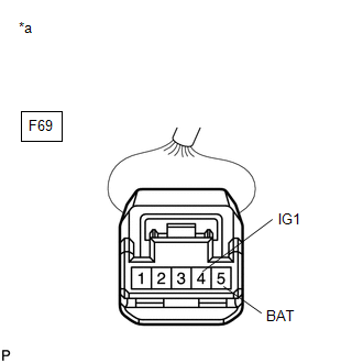
(c) Disconnect the E69 steering angle sensor connector.
(d) Measure the voltage according to the value(s) in the table below.
Standard Voltage:
|
Tester Connection |
Condition |
Specified Condition |
|---|---|---|
|
E69-5 (BAT) - Body ground |
Always |
11 to 14 V |
|
E69-4 (IG1) - Body ground |
Ignition switch ON |
11 to 14 V |
|
Result |
Proceed to |
|---|---|
|
OK |
A |
|
NG |
B |
| B | .gif) |
REPAIR OR REPLACE HARNESS OR CONNECTOR (POWER SOURCE CIRCUIT) |
|
.gif)
|
2. |
CHECK HARNESS AND CONNECTOR (GROUND TERMINAL) |
|
(a) Turn the ignition switch off. |
|
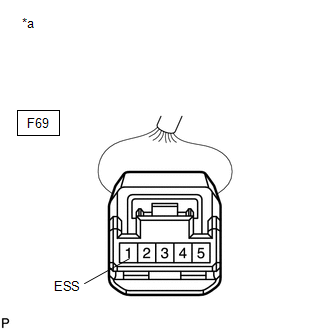
(b) Measure the resistance according to the value(s) in the table below.
Standard Resistance:
|
Tester Connection |
Condition |
Specified Condition |
|---|---|---|
|
E69-1 (ESS) - Body ground |
Always |
Below 1 Ω |
HINT:
If troubleshooting has been carried out according to Problem Symptoms Table, refer back to the table and proceed to the next step before replacing parts.
Click here
| OK | |
REPLACE STEERING ANGLE SENSOR |
| NG | |
REPAIR OR REPLACE HARNESS OR CONNECTOR (GROUND CIRCUIT) |
 Brake Pedal Load Sensing Switch OFF Stuck Malfunction (C1430,C1431)
DESCRIPTION
The brake pedal load sensing switch turns on when the brake pedal is depressed
with a force exceeding a predetermined level.
The skid control ECU uses this circuit to detect if the bra ...
 Steering Angle Sensor Internal Circuit (C1433)
DESCRIPTION
This DTC is stored when the skid control ECU (brake actuator assembly) receives
an internal malfunction signal from the steering angle sensor.
DTC No.
Detection I ...
Other materials:
Toyota CH-R Service Manual > Lighting System: System Description
SYSTEM DESCRIPTION
AUTOMATIC LIGHT CONTROL SYSTEM
(a) When the light control switch is in the AUTO position, the automatic light
control system detects ambient light levels and controls the low beam headlights,
clearance lights, taillights and license plate lights.
LIGHT AUTO TURN-OFF SYSTEM ...
Toyota CH-R Service Manual > Audio / Video: Roof Antenna
Components
COMPONENTS
ILLUSTRATION
*1
ROOF ANTENNA ASSEMBLY
*2
ANTENNA OUTER COVER
*3
HOLDER
*4
SEAL
N*m (kgf*cm, ft.*lbf): Specified torque
●
Non-re ...
Toyota CH-R Owners Manual
- For safety and security
- Instrument cluster
- Operation of each component
- Driving
- Interior features
- Maintenance and care
- When trouble arises
- Vehicle specifications
- For owners
Toyota CH-R Service Manual
- Introduction
- Maintenance
- Audio / Video
- Cellular Communication
- Navigation / Multi Info Display
- Park Assist / Monitoring
- Brake (front)
- Brake (rear)
- Brake Control / Dynamic Control Systems
- Brake System (other)
- Parking Brake
- Axle And Differential
- Drive Shaft / Propeller Shaft
- K114 Cvt
- 3zr-fae Battery / Charging
- Networking
- Power Distribution
- Power Assist Systems
- Steering Column
- Steering Gear / Linkage
- Alignment / Handling Diagnosis
- Front Suspension
- Rear Suspension
- Tire / Wheel
- Tire Pressure Monitoring
- Door / Hatch
- Exterior Panels / Trim
- Horn
- Lighting (ext)
- Mirror (ext)
- Window / Glass
- Wiper / Washer
- Door Lock
- Heating / Air Conditioning
- Interior Panels / Trim
- Lighting (int)
- Meter / Gauge / Display
- Mirror (int)
- Power Outlets (int)
- Pre-collision
- Seat
- Seat Belt
- Supplemental Restraint Systems
- Theft Deterrent / Keyless Entry

0.0085