Toyota CH-R Service Manual: Open or Short in Brake Pedal Load Sensing Switch (C1429)
DESCRIPTION
The brake pedal load sensing switch turns on when the brake pedal is depressed with a force exceeding a predetermined level.
The skid control ECU uses this circuit to detect if the brake pedal is depressed or not.
|
DTC No. |
Detection Item |
DTC Detection Condition |
Trouble Area |
|---|---|---|---|
|
C1429 |
Open or Short in Brake Pedal Load Sensing Switch |
An open or short in the brake pedal load sensing switch circuit continues for 0.5 seconds or more. |
|
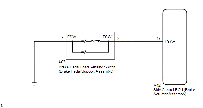
WIRING DIAGRAM
CAUTION / NOTICE / HINT
HINT:
When C1249, C1425 and/or C1426 is output together with C1429, inspect and repair
the trouble areas indicated by C1249, C1425 and/or C1426 first: (Click here
.gif) ), (Click here
), and/or Click here
)).
), (Click here
), and/or Click here
)).
PROCEDURE
|
1. |
READ VALUE USING TECHSTREAM (BRAKE PEDAL LOAD SENSING SWITCH) |
(a) Connect the Techstream to the DLC3.
(b) Turn the ignition switch to ON.
(c) Select the Data List using the Techstream.
Click here
|
Tester Display |
Measurement Item |
Range |
Normal Condition |
Diagnostic Note |
|---|---|---|---|---|
|
Brake Pedal Load Sensing SW |
Brake pedal load sensing switch |
ON or OFF |
ON: Brake pedal depressed beyond a specified point OFF: Brake pedal not depressed beyond a specified point |
- |
(d) Check that the brake pedal load sensing switch display observed on the Techstream changes according to brake pedal operation.
OK:
The Techstream displays ON or OFF according to brake pedal operation.
| NG | .gif) |
GO TO STEP 3 |
|
.gif)
|
2. |
RECONFIRM DTC |
(a) Turn the ignition switch off.
(b) Clear the DTCs.
Click here
(c) Turn the ignition switch off.
(d) Start the engine.
(e) Perform a road test.
(f) Check if the same DTC is output.
Click here
|
Result |
Proceed to |
|---|---|
|
DTC C1429 is not output. |
A |
|
DTC C1429 is output. |
B |
| A | |
USE SIMULATION METHOD TO CHECK
|
| B | |
REPLACE BRAKE ACTUATOR ASSEMBLY |
|
3. |
INSPECT BRAKE PEDAL LOAD SENSING SWITCH |
|
(a) Turn the ignition switch off. |
|
(b) Make sure that there is no looseness at the locking part and the connecting part of the connector.
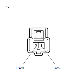
(c) Disconnect the A63 brake pedal load sensing switch connector.
NOTICE:
- Do not remove the brake pedal load sensing switch from the brake pedal support assembly.
- When there is a malfunction in the brake pedal load sensing switch, replace the brake pedal support assembly.
(d) Measure the resistance according to the value(s) in the table below.
Standard Resistance:
|
Tester Connection |
Condition |
Specified Condition |
|---|---|---|
|
2 (FSW+) - 1 (FSW-) |
Switch OFF (Brake pedal depressed) |
950 to 1050 Ω |
|
2 (FSW+) - 1 (FSW-) |
Switch ON (Brake pedal released) |
203 to 223 Ω |
| NG | |
REPLACE BRAKE PEDAL SUPPORT ASSEMBLY |
|
|
4. |
CHECK HARNESS AND CONNECTOR (BRAKE ACTUATOR ASSEMBLY - BRAKE PEDAL LOAD SENSING SWITCH) |
(a) Make sure that there is no looseness at the locking part and the connecting part of the connector.
(b) Disconnect the A42 skid control ECU (brake actuator assembly) connector.
(c) Measure the resistance according to the value(s) in the table below.
Standard Resistance:
|
Tester Connection |
Condition |
Specified Condition |
|---|---|---|
|
A42-17 (FSW+) - A63-2 (FSW+) |
Always |
Below 1 Ω |
|
A42-17 (FSW+) - Body ground |
Always |
10 kΩ or higher |
|
A63-2 (FSW+) - Body ground |
Always |
10 kΩ or higher |
|
A63-1 (FSW-) - Body ground |
Always |
Below 1 Ω |
| OK | |
REPLACE BRAKE ACTUATOR ASSEMBLY |
| NG | |
REPAIR OR REPLACE HARNESS OR CONNECTOR |
 Motor Circuit Malfunction (C1428)
DESCRIPTION
This DTC is stored when the skid control ECU (brake actuator assembly) judges
that an abnormality occurred in the circuit used to operate the pump motor.
DTC No.
...
 Brake Pedal Load Sensing Switch OFF Stuck Malfunction (C1430,C1431)
DESCRIPTION
The brake pedal load sensing switch turns on when the brake pedal is depressed
with a force exceeding a predetermined level.
The skid control ECU uses this circuit to detect if the bra ...
Other materials:
Toyota CH-R Service Manual > Air Conditioning System(for Automatic Air Conditioning System With Top-mounted
Air Conditioner Pressure Sensor): How To Proceed With Troubleshooting
CAUTION / NOTICE / HINT
HINT:
Use the following procedure to troubleshoot the air conditioning system.
*: Use the Techstream.
PROCEDURE
1.
VEHICLE BROUGHT TO WORKSHOP
NEXT
...
Toyota CH-R Service Manual > Blind Spot Monitor System: Power Source Circuit
DESCRIPTION
This circuit provides power to operate the blind spot monitor sensor.
WIRING DIAGRAM
CAUTION / NOTICE / HINT
NOTICE:
Inspect the fuses for circuits related to this system before performing the following
procedure.
PROCEDURE
1.
CHECK HARNESS AND CONNECTOR ...
Toyota C-HR (AX20) 2023-2026 Owner's Manual
Toyota CH-R Owners Manual
- For safety and security
- Instrument cluster
- Operation of each component
- Driving
- Interior features
- Maintenance and care
- When trouble arises
- Vehicle specifications
- For owners
Toyota CH-R Service Manual
- Introduction
- Maintenance
- Audio / Video
- Cellular Communication
- Navigation / Multi Info Display
- Park Assist / Monitoring
- Brake (front)
- Brake (rear)
- Brake Control / Dynamic Control Systems
- Brake System (other)
- Parking Brake
- Axle And Differential
- Drive Shaft / Propeller Shaft
- K114 Cvt
- 3zr-fae Battery / Charging
- Networking
- Power Distribution
- Power Assist Systems
- Steering Column
- Steering Gear / Linkage
- Alignment / Handling Diagnosis
- Front Suspension
- Rear Suspension
- Tire / Wheel
- Tire Pressure Monitoring
- Door / Hatch
- Exterior Panels / Trim
- Horn
- Lighting (ext)
- Mirror (ext)
- Window / Glass
- Wiper / Washer
- Door Lock
- Heating / Air Conditioning
- Interior Panels / Trim
- Lighting (int)
- Meter / Gauge / Display
- Mirror (int)
- Power Outlets (int)
- Pre-collision
- Seat
- Seat Belt
- Supplemental Restraint Systems
- Theft Deterrent / Keyless Entry

0.0107