Toyota CH-R Service Manual: Radio Receiver Power Source Circuit
DESCRIPTION
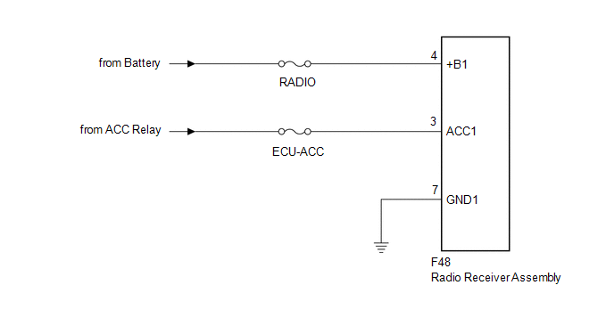
This is the power source circuit to operate the radio receiver assembly.
WIRING DIAGRAM
CAUTION / NOTICE / HINT
NOTICE:
Inspect the fuses for circuits related to this system before performing the following procedure.
PROCEDURE
|
1. |
CHECK HARNESS AND CONNECTOR (RADIO RECEIVER ASSEMBLY POWER SOURCE) |
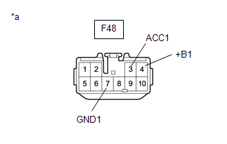
(a) Disconnect the radio receiver assembly connector.
|
(b) Measure the resistance according to the value(s) in the table below. Standard Resistance:
|
|
(c) Measure the voltage according to the value(s) in the table below.
Standard Voltage:
|
Tester Connection |
Condition |
Specified Condition |
|---|---|---|
|
F48-4 (+B1) - F48-7 (GND1) |
Always |
11 to 14 V |
|
F48-3 (ACC1) - F48-7 (GND1) |
Ignition switch ACC |
11 to 14 V |
| OK | .gif) |
PROCEED TO NEXT SUSPECTED AREA SHOWN IN PROBLEM SYMPTOMS TABLE |
| NG | |
REPAIR OR REPLACE HARNESS OR CONNECTOR |
 Microphone Circuit between Microphone and Radio Receiver
DESCRIPTION
The radio receiver assembly and map light assembly (telephone microphone assembly)
are connected to each other using the microphone connection detection signal lines.
Using this circui ...

Other materials:
Toyota CH-R Service Manual > Lighting (int): Map Light Bulb
Replacement
REPLACEMENT
PROCEDURE
1. REMOVE NO. 1 MAP LIGHT LENS
Click here
2. REMOVE MAP LIGHT BULB
(a) Remove the 2 map light bulbs as shown in the illustration.
Remove in this Direction
3. INSTALL MAP LIGHT BULB
(a) Install the 2 map light bulbs as show ...
Toyota CH-R Service Manual > 3zr-fae Battery: Components
COMPONENTS
ILLUSTRATION
*1
BATTERY
*2
NO. 2 BATTERY CLAMP
*3
POSITIVE BATTERY TERMINAL
*4
NEGATIVE BATTERY TERMINAL
*5
FUSIBLE LINK COVER
*6
BATTERY INS ...
Toyota C-HR (AX20) 2023-2026 Owner's Manual
Toyota CH-R Owners Manual
- For safety and security
- Instrument cluster
- Operation of each component
- Driving
- Interior features
- Maintenance and care
- When trouble arises
- Vehicle specifications
- For owners
Toyota CH-R Service Manual
- Introduction
- Maintenance
- Audio / Video
- Cellular Communication
- Navigation / Multi Info Display
- Park Assist / Monitoring
- Brake (front)
- Brake (rear)
- Brake Control / Dynamic Control Systems
- Brake System (other)
- Parking Brake
- Axle And Differential
- Drive Shaft / Propeller Shaft
- K114 Cvt
- 3zr-fae Battery / Charging
- Networking
- Power Distribution
- Power Assist Systems
- Steering Column
- Steering Gear / Linkage
- Alignment / Handling Diagnosis
- Front Suspension
- Rear Suspension
- Tire / Wheel
- Tire Pressure Monitoring
- Door / Hatch
- Exterior Panels / Trim
- Horn
- Lighting (ext)
- Mirror (ext)
- Window / Glass
- Wiper / Washer
- Door Lock
- Heating / Air Conditioning
- Interior Panels / Trim
- Lighting (int)
- Meter / Gauge / Display
- Mirror (int)
- Power Outlets (int)
- Pre-collision
- Seat
- Seat Belt
- Supplemental Restraint Systems
- Theft Deterrent / Keyless Entry

0.0079