Toyota CH-R Service Manual: Reassembly
REASSEMBLY
CAUTION / NOTICE / HINT
NOTICE:
- Do not drop the power steering ECU assembly, strike it with tools or subject it to impacts.
- If the power steering ECU assembly is subjected to an impact, replace it with a new one.
- Do not pull the wire harness.
- Do not allow any moisture to come into contact with the power steering ECU assembly.
- Do not loosen any bolts not mentioned in the procedure.
- Do not allow any foreign matter to contaminate the power steering ECU assembly.
PROCEDURE
1. INSTALL ELECTRIC POWER STEERING MOTOR SHAFT DAMPER
Click here
.gif)
2. INSTALL POWER STEERING ECU ASSEMBLY
Click here
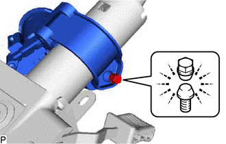
3. INSTALL STEERING LOCK ACTUATOR ASSEMBLY (w/ Smart Key System)
HINT:
When replacing the steering lock actuator assembly, refer to Registration.
Click here
|
(a) Install the steering lock actuator assembly with the tapered-head bolt. |
|
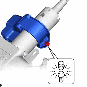
(b) Tighten the tapered-head bolt until the bolt head breaks off.
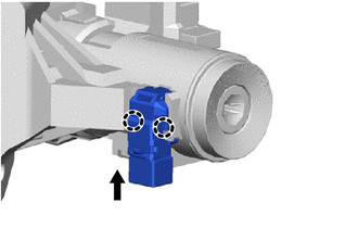
4. INSTALL KEY INTERLOCK SOLENOID (w/o Smart Key System)
|
(a) Install the key interlock solenoid to the upper steering column bracket assembly with the screw. |
|
.png)
5. INSTALL IGNITION OR STARTER SWITCH ASSEMBLY (w/o Smart Key System)
|
(a) Install the ignition or starter switch assembly with the 2 screws. |
|
.png)
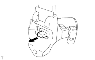
6. INSTALL UN-LOCK WARNING SWITCH ASSEMBLY (w/o Smart Key System)
|
(a) Engage the 2 claws to install the un-lock warning switch assembly to the upper steering column bracket assembly. |
|
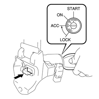
7. INSTALL IGNITION SWITCH LOCK CYLINDER ASSEMBLY (w/o Smart Key System)
(a) Make sure that the ignition switch lock cylinder assembly is in the ACC position.
(b) Install the ignition switch lock cylinder assembly.
8. INSPECT STEERING LOCK OPERATION (w/o Smart Key System)
|
(a) Check that the steering lock mechanism is activated when the key is removed. |
|
|
(b) Check that the steering lock mechanism is deactivated when the key is inserted and turned to the ACC position. If there is any abnormality, replace the ignition switch lock cylinder assembly. |
|
9. INSTALL UPPER STEERING COLUMN BRACKET WITH SWITCH ASSEMBLY (w/o Smart Key System)
|
(a) Install the upper steering column bracket with switch assembly with the tapered-head bolt. |
|
(b) Tighten the tapered-head bolt until the bolt head breaks off.
10. INSTALL TRANSPONDER KEY COIL (w/o Smart Key System)
Click here
 Installation
INSTALLATION
PROCEDURE
1. ALIGN FRONT WHEELS FACING STRAIGHT AHEAD
2. INSTALL STEERING COLUMN ASSEMBLY
NOTICE:
Make sure that the wire harness is not interfering with the steering column assembly ...

Other materials:
Toyota CH-R Service Manual > Smart Key System(for Entry Function): Entry Exterior Alarm does not Sound
DESCRIPTION
The smart key system (for Entry Function) uses the wireless door lock buzzer
to perform various vehicle exterior warnings. When the conditions of each warning
are met, the certification ECU (smart key ECU assembly) sends a buzzer activation
request signal to the main body ECU (mul ...
Toyota CH-R Service Manual > Front Speed Sensor: Installation
INSTALLATION
CAUTION / NOTICE / HINT
HINT:
Use the same procedure for the RH side and LH side.
The following procedure is for the LH side.
The front speed sensor rotor is a component of the front axle hub sub-assembly.
If the front speed sensor rotor is malfunctioning, replace ...
Toyota C-HR (AX20) 2023-2026 Owner's Manual
Toyota CH-R Owners Manual
- For safety and security
- Instrument cluster
- Operation of each component
- Driving
- Interior features
- Maintenance and care
- When trouble arises
- Vehicle specifications
- For owners
Toyota CH-R Service Manual
- Introduction
- Maintenance
- Audio / Video
- Cellular Communication
- Navigation / Multi Info Display
- Park Assist / Monitoring
- Brake (front)
- Brake (rear)
- Brake Control / Dynamic Control Systems
- Brake System (other)
- Parking Brake
- Axle And Differential
- Drive Shaft / Propeller Shaft
- K114 Cvt
- 3zr-fae Battery / Charging
- Networking
- Power Distribution
- Power Assist Systems
- Steering Column
- Steering Gear / Linkage
- Alignment / Handling Diagnosis
- Front Suspension
- Rear Suspension
- Tire / Wheel
- Tire Pressure Monitoring
- Door / Hatch
- Exterior Panels / Trim
- Horn
- Lighting (ext)
- Mirror (ext)
- Window / Glass
- Wiper / Washer
- Door Lock
- Heating / Air Conditioning
- Interior Panels / Trim
- Lighting (int)
- Meter / Gauge / Display
- Mirror (int)
- Power Outlets (int)
- Pre-collision
- Seat
- Seat Belt
- Supplemental Restraint Systems
- Theft Deterrent / Keyless Entry

0.0066