Toyota CH-R Service Manual: Removal
REMOVAL
CAUTION / NOTICE / HINT
The necessary procedures(adjustment, calibration, initialization, or registration) that must be performed after parts are removed, installed, or replaced during the generator assembly removal/installation are shown below.
Necessary Procedure After Parts Removed/Installed/Replaced|
Replacement Part or Procedure |
Necessary Procedure |
Effect/Inoperative when not Performed |
Link |
|---|---|---|---|
|
Disconnect cable from negative battery terminal |
Initialize back door lock |
Power door lock control system |
|
|
Memorize steering angle neutral point |
Lane departure alert system (w/ Steering Control) |
|
|
|
Pre-collision system |
PROCEDURE
1. PRECAUTION
NOTICE:
After turning the ignition switch off, waiting time may be required before disconnecting the cable from the negative (-) battery terminal. Therefore, make sure to read the disconnecting the cable from the negative (-) battery terminal notices before proceeding with work.
Click here
.gif)
2. DISCONNECT CABLE FROM NEGATIVE BATTERY TERMINAL
Click here
NOTICE:
When disconnecting the cable, some systems need to be initialized after the cable is reconnected.
Click here
3. REMOVE FAN AND GENERATOR V BELT
Click here
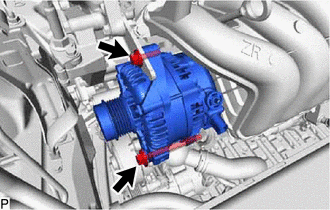
4. REMOVE GENERATOR ASSEMBLY
|
(a) Remove the terminal cap from the generator assembly. |
|
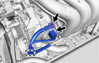
(b) Remove the nut to disconnect the engine wire from terminal B.
(c) Disconnect the generator assembly connector.
(d) Disengage the clamp to disconnect the wire harness from the wire harness clamp bracket.
|
(e) Remove the 2 bolts and generator assembly. |
|
|
(f) Remove the bolt and wire harness clamp bracket from the generator assembly. |
|
 Disassembly
DISASSEMBLY
PROCEDURE
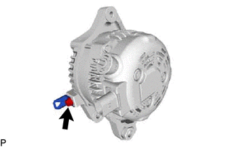
1. REMOVE GENERATOR PULLEY CAP
(a) Using a screwdriver, remove the generator pulley cap from the generator
pulley with clutch.
NOTICE:
Do not reuse the ge ...
 Inspection
INSPECTION
PROCEDURE
1. INSPECT GENERATOR PULLEY WITH CLUTCH
(a) Hold the center of the generator pulley with clutch, and confirm
that the outer ring turns counterclockwise and does ...
Other materials:
Toyota CH-R Service Manual > How To Troubleshoot Ecu Controlled Systems: How To Proceed With Troubleshooting
HOW TO PROCEED WITH TROUBLESHOOTING
OPERATION FLOW
HINT:
Perform troubleshooting in accordance with the procedure below. The following
is an outline of basic troubleshooting procedure. Confirm the troubleshooting procedure
for the circuit you are working on before beginning troubleshooting.
...
Toyota CH-R Owners Manual > Maintenance and care: Cleaning and protecting the vehicle exterior
Perform the following to protect the vehicle and maintain it in prime
condition:
Working from top to bottom, liberally apply water to the vehicle body, wheel
wells and underside of the vehicle to remove any dirt and dust.
Wash the vehicle body using a sponge or soft cloth, such as a chamo ...
Toyota C-HR (AX20) 2023-2026 Owner's Manual
Toyota CH-R Owners Manual
- For safety and security
- Instrument cluster
- Operation of each component
- Driving
- Interior features
- Maintenance and care
- When trouble arises
- Vehicle specifications
- For owners
Toyota CH-R Service Manual
- Introduction
- Maintenance
- Audio / Video
- Cellular Communication
- Navigation / Multi Info Display
- Park Assist / Monitoring
- Brake (front)
- Brake (rear)
- Brake Control / Dynamic Control Systems
- Brake System (other)
- Parking Brake
- Axle And Differential
- Drive Shaft / Propeller Shaft
- K114 Cvt
- 3zr-fae Battery / Charging
- Networking
- Power Distribution
- Power Assist Systems
- Steering Column
- Steering Gear / Linkage
- Alignment / Handling Diagnosis
- Front Suspension
- Rear Suspension
- Tire / Wheel
- Tire Pressure Monitoring
- Door / Hatch
- Exterior Panels / Trim
- Horn
- Lighting (ext)
- Mirror (ext)
- Window / Glass
- Wiper / Washer
- Door Lock
- Heating / Air Conditioning
- Interior Panels / Trim
- Lighting (int)
- Meter / Gauge / Display
- Mirror (int)
- Power Outlets (int)
- Pre-collision
- Seat
- Seat Belt
- Supplemental Restraint Systems
- Theft Deterrent / Keyless Entry

0.008