Toyota CH-R Service Manual: Disassembly
DISASSEMBLY
PROCEDURE
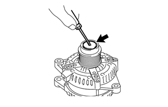
1. REMOVE GENERATOR PULLEY CAP
|
(a) Using a screwdriver, remove the generator pulley cap from the generator pulley with clutch. NOTICE: Do not reuse the generator pulley cap. |
|
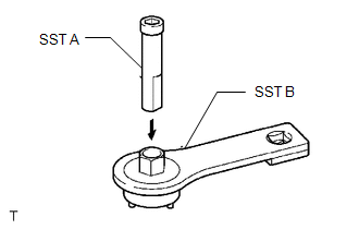
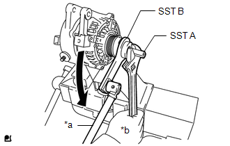
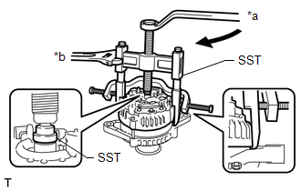
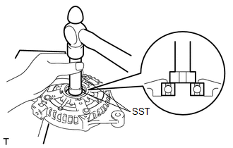
2. REMOVE GENERATOR PULLEY WITH CLUTCH
(a) Secure the generator drive end frame in a vise between aluminum plates.
|
(b) Confirm SST (A) and (B) shown in the illustration. SST: 09820-63021 |
|
|
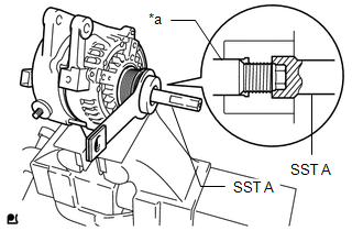
(c) Place the rotor shaft end into SST (A). |
|
|
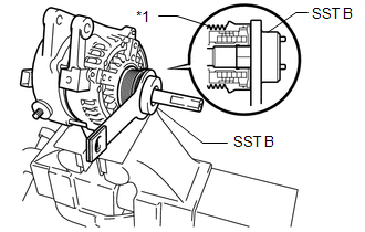
(d) Fit SST (B) to the generator pulley with clutch. |
|
|
(e) Loosen the generator pulley with clutch by turning SST (B) as shown in the illustration. NOTICE:
|
|
(f) Remove SST from the generator pulley with clutch.
(g) Remove the generator pulley with clutch from the rotor shaft.
(h) Remove the generator assembly from the vise.
3. REMOVE GENERATOR REAR END COVER
|
(a) Place the generator assembly on the generator pulley with clutch. |
|
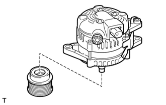
|
(b) Remove the 3 bolts and generator rear end cover from the generator coil assembly. |
|
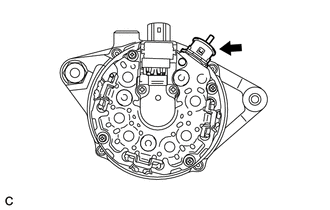
4. REMOVE GENERATOR TERMINAL INSULATOR
|
(a) Remove the generator terminal insulator from the generator coil assembly. |
|
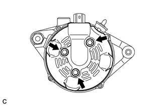
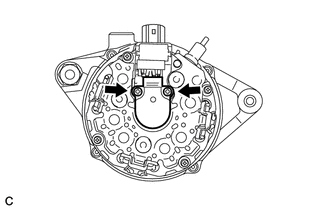
5. REMOVE GENERATOR BRUSH HOLDER ASSEMBLY
|
(a) Remove the 2 screws and generator brush holder assembly from the generator coil assembly. |
|
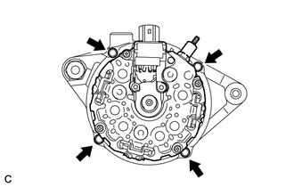
6. REMOVE GENERATOR COIL ASSEMBLY
|
(a) Remove the 4 bolts. |
|
|
(b) Using SST, remove the generator coil assembly. SST: 09950-40011 09951-04020 09952-04010 09953-04020 09954-04010 09955-04071 09957-04010 |
|
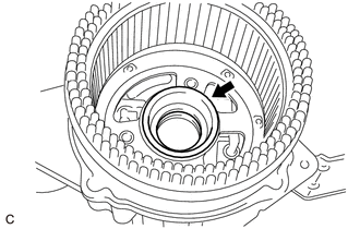
|
(c) Remove the bearing cover packing. NOTICE: If the bearing cover packing breaks, remove the broken pieces completely. HINT: The bearing cover packing may be installed on the generator rotor assembly. |
|
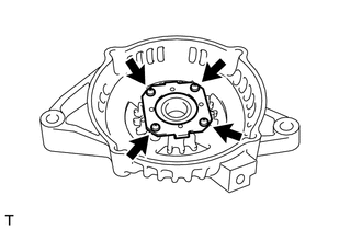
7. REMOVE GENERATOR ROTOR ASSEMBLY
|
(a) Remove the generator rotor assembly from the generator drive end frame. |
|
8. INSPECT GENERATOR DRIVE END FRAME BEARING
Click here
.gif)
9. REMOVE GENERATOR DRIVE END FRAME BEARING
|
(a) Remove the 4 screws and retainer plate from the generator drive end frame. |
|
|
(b) Using SST and a hammer, tap out the generator drive end frame bearing. SST: 09950-60010 09951-00250 SST: 09950-70010 09951-07100 |
|
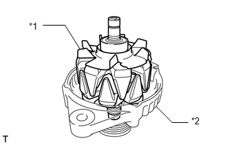
 Components
COMPONENTS
ILLUSTRATION
*1
GENERATOR ASSEMBLY
*2
TERMINAL CAP
*3
WIRE HARNESS CLAMP BRACKET
-
-
...
 Removal
REMOVAL
CAUTION / NOTICE / HINT
The necessary procedures(adjustment, calibration, initialization, or registration)
that must be performed after parts are removed, installed, or replaced during the ...
Other materials:
Toyota CH-R Service Manual > Power Window Control System: Improper Operation
DESCRIPTION
In cases where a door window closed (closes) by itself even though a window closing
operation was not performed, possible causes include vehicle-side malfunction, environmental
causes, or operation by the customer (including other passengers in the vehicle).
By using the operation ...
Toyota CH-R Service Manual > Power Steering System: How To Proceed With Troubleshooting
CAUTION / NOTICE / HINT
HINT:
Use these procedures to troubleshoot the power steering system.
*: Use the Techstream.
PROCEDURE
1.
VEHICLE BROUGHT TO WORKSHOP
NEXT
2.
...
Toyota C-HR (AX20) 2023-2026 Owner's Manual
Toyota CH-R Owners Manual
- For safety and security
- Instrument cluster
- Operation of each component
- Driving
- Interior features
- Maintenance and care
- When trouble arises
- Vehicle specifications
- For owners
Toyota CH-R Service Manual
- Introduction
- Maintenance
- Audio / Video
- Cellular Communication
- Navigation / Multi Info Display
- Park Assist / Monitoring
- Brake (front)
- Brake (rear)
- Brake Control / Dynamic Control Systems
- Brake System (other)
- Parking Brake
- Axle And Differential
- Drive Shaft / Propeller Shaft
- K114 Cvt
- 3zr-fae Battery / Charging
- Networking
- Power Distribution
- Power Assist Systems
- Steering Column
- Steering Gear / Linkage
- Alignment / Handling Diagnosis
- Front Suspension
- Rear Suspension
- Tire / Wheel
- Tire Pressure Monitoring
- Door / Hatch
- Exterior Panels / Trim
- Horn
- Lighting (ext)
- Mirror (ext)
- Window / Glass
- Wiper / Washer
- Door Lock
- Heating / Air Conditioning
- Interior Panels / Trim
- Lighting (int)
- Meter / Gauge / Display
- Mirror (int)
- Power Outlets (int)
- Pre-collision
- Seat
- Seat Belt
- Supplemental Restraint Systems
- Theft Deterrent / Keyless Entry

0.0101