Toyota CH-R Service Manual: Inspection
INSPECTION
PROCEDURE
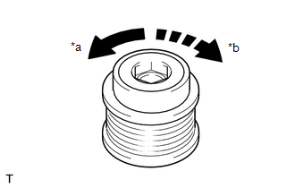
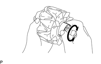
1. INSPECT GENERATOR PULLEY WITH CLUTCH
|
(a) Hold the center of the generator pulley with clutch, and confirm that the outer ring turns counterclockwise and does not turn clockwise. OK: The outer ring turns counterclockwise and does not turn clockwise. If the result is not as specified, replace the generator pulley with clutch. |
|
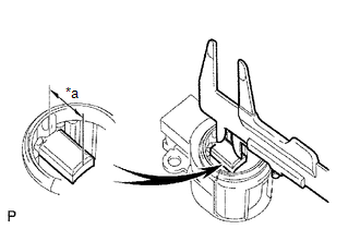
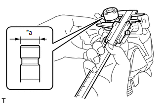
2. INSPECT GENERATOR BRUSH HOLDER ASSEMBLY
|
(a) Using a vernier caliper, measure the length of the exposed brushes. Standard Exposed Brush Length: 9.5 to 11.5 mm (0.374 to 0.453 in.) Minimum Exposed Brush Length: 4.5 mm (0.177 in.) If the brush length is less than the minimum, replace the generator brush holder assembly. |
|
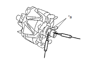
3. INSPECT GENERATOR ROTOR ASSEMBLY
|
(a) Check the generator rotor assembly for an open circuit. (1) Measure the resistance according to the value(s) in the table below. Standard Resistance:
If the result is not as specified, replace the generator rotor assembly. |
|
|
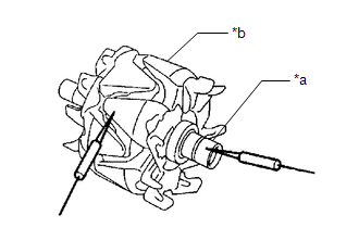
(b) Check the generator rotor assembly for a short to ground. (1) Measure the resistance according to the value(s) in the table below. Standard Resistance:
If the result is not as specified, replace the generator rotor assembly. |
|
|
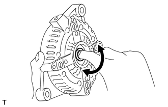
(c) Check that the generator rotor bearing is not rough or worn and that it rotates smoothly. If the generator rotor bearing is rough or worn, or does not rotate smoothly, replace the generator rotor assembly. |
|
|
(d) Check the slip ring. (1) Check that the slip rings are not rough or scored. If the slip rings are rough or scored, replace the generator rotor assembly. (2) Using a vernier caliper, measure the slip ring diameter. Standard Diameter: 14.2 to 14.8 mm (0.559 to 0.583 in.) Minimum Diameter: 14.0 mm (0.551 in.) If the diameter is less than the minimum, replace the generator rotor assembly. |
|
4. INSPECT GENERATOR DRIVE END FRAME BEARING
|
(a) Check that the generator drive end frame bearing is not rough or worn and that it rotates smoothly. If the generator drive end frame bearing is rough or worn, or does not rotate smoothly, replace the generator drive end frame bearing. |
|
 Removal
REMOVAL
CAUTION / NOTICE / HINT
The necessary procedures(adjustment, calibration, initialization, or registration)
that must be performed after parts are removed, installed, or replaced during the ...
 Installation
INSTALLATION
PROCEDURE
1. INSTALL GENERATOR ASSEMBLY
(a) Install the wire harness clamp bracket to the generator assembly with the
bolt.
Torque:
8.0 N·m {82 kgf·cm, 71 in·lbf}
( ...
Other materials:
Toyota CH-R Service Manual > Steering Pad: On-vehicle Inspection
ON-VEHICLE INSPECTION
CAUTION / NOTICE / HINT
CAUTION:
Be sure to correctly follow the removal and installation procedures for the horn
button assembly.
PROCEDURE
1. INSPECT HORN BUTTON ASSEMBLY (for Vehicle not Involved in Collision)
(a) Perform a diagnostic system check.
Click here
(b) ...
Toyota CH-R Service Manual > Maintenance: Tire And Wheel
Components
COMPONENTS
ILLUSTRATION
*A
for Steel Wheel
-
-
*1
WHEEL ASSEMBLY
*2
WHEEL CAP
*3
AXLE HUB NUT
-
-
Tightening tor ...
Toyota C-HR (AX20) 2023-2026 Owner's Manual
Toyota CH-R Owners Manual
- For safety and security
- Instrument cluster
- Operation of each component
- Driving
- Interior features
- Maintenance and care
- When trouble arises
- Vehicle specifications
- For owners
Toyota CH-R Service Manual
- Introduction
- Maintenance
- Audio / Video
- Cellular Communication
- Navigation / Multi Info Display
- Park Assist / Monitoring
- Brake (front)
- Brake (rear)
- Brake Control / Dynamic Control Systems
- Brake System (other)
- Parking Brake
- Axle And Differential
- Drive Shaft / Propeller Shaft
- K114 Cvt
- 3zr-fae Battery / Charging
- Networking
- Power Distribution
- Power Assist Systems
- Steering Column
- Steering Gear / Linkage
- Alignment / Handling Diagnosis
- Front Suspension
- Rear Suspension
- Tire / Wheel
- Tire Pressure Monitoring
- Door / Hatch
- Exterior Panels / Trim
- Horn
- Lighting (ext)
- Mirror (ext)
- Window / Glass
- Wiper / Washer
- Door Lock
- Heating / Air Conditioning
- Interior Panels / Trim
- Lighting (int)
- Meter / Gauge / Display
- Mirror (int)
- Power Outlets (int)
- Pre-collision
- Seat
- Seat Belt
- Supplemental Restraint Systems
- Theft Deterrent / Keyless Entry

0.0074