Toyota CH-R Service Manual: Installation
INSTALLATION
PROCEDURE
1. INSTALL GENERATOR ASSEMBLY
(a) Install the wire harness clamp bracket to the generator assembly with the bolt.
Torque:
8.0 N·m {82 kgf·cm, 71 in·lbf}
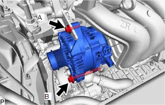
|
(b) Install the generator assembly with the 2 bolts. Torque: Bolt A : 25 N·m {255 kgf·cm, 18 ft·lbf} Bolt B : 43 N·m {438 kgf·cm, 32 ft·lbf} |
|
(c) Engage the clamp to connect the engine wire to the wire harness clamp bracket.
(d) Connect the generator assembly connector.
(e) Connect the engine wire to terminal B with the nut.
Torque:
9.8 N·m {100 kgf·cm, 87 in·lbf}
(f) Install the terminal cap to the generator assembly.
2. INSTALL FAN AND GENERATOR V BELT
Click here
.gif)
3. CONNECT CABLE TO NEGATIVE BATTERY TERMINAL
Click here
NOTICE:
When disconnecting the cable, some systems need to be initialized after the cable is reconnected.
Click here
 Inspection
INSPECTION
PROCEDURE
1. INSPECT GENERATOR PULLEY WITH CLUTCH
(a) Hold the center of the generator pulley with clutch, and confirm
that the outer ring turns counterclockwise and does ...
 Reassembly
REASSEMBLY
PROCEDURE
1. INSTALL GENERATOR DRIVE END FRAME BEARING
(a) Using SST and a press, install a new generator drive end frame bearing.
SST: 09950-60010
09951-00470
SST: 0 ...
Other materials:
Toyota CH-R Service Manual > Audio And Visual System(for Radio Receiver Type): Precaution
PRECAUTION
IGNITION SWITCH EXPRESSIONS
(a) The type of ignition switch used on this model differs depending on the specifications
of the vehicle. The expressions listed in the table below are used in this section.
Expression
Ignition Switch
(Position)
Engine ...
Toyota CH-R Service Manual > Key Reminder Warning System: Operation Check
OPERATION CHECK
CHECK FUNCTION
(a) Check that the key reminder warning buzzer sounds.
(1) With the driver door closed, insert the key into the ignition key cylinder
and then make sure that the ignition switch is off or ACC.
(2) Check that the buzzer sounds intermittently if the driver door is ...
Toyota C-HR (AX20) 2023-2026 Owner's Manual
Toyota CH-R Owners Manual
- For safety and security
- Instrument cluster
- Operation of each component
- Driving
- Interior features
- Maintenance and care
- When trouble arises
- Vehicle specifications
- For owners
Toyota CH-R Service Manual
- Introduction
- Maintenance
- Audio / Video
- Cellular Communication
- Navigation / Multi Info Display
- Park Assist / Monitoring
- Brake (front)
- Brake (rear)
- Brake Control / Dynamic Control Systems
- Brake System (other)
- Parking Brake
- Axle And Differential
- Drive Shaft / Propeller Shaft
- K114 Cvt
- 3zr-fae Battery / Charging
- Networking
- Power Distribution
- Power Assist Systems
- Steering Column
- Steering Gear / Linkage
- Alignment / Handling Diagnosis
- Front Suspension
- Rear Suspension
- Tire / Wheel
- Tire Pressure Monitoring
- Door / Hatch
- Exterior Panels / Trim
- Horn
- Lighting (ext)
- Mirror (ext)
- Window / Glass
- Wiper / Washer
- Door Lock
- Heating / Air Conditioning
- Interior Panels / Trim
- Lighting (int)
- Meter / Gauge / Display
- Mirror (int)
- Power Outlets (int)
- Pre-collision
- Seat
- Seat Belt
- Supplemental Restraint Systems
- Theft Deterrent / Keyless Entry

0.0086