Toyota CH-R Service Manual: Reassembly
REASSEMBLY
PROCEDURE
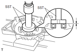
1. INSTALL GENERATOR DRIVE END FRAME BEARING
|
(a) Using SST and a press, install a new generator drive end frame bearing. SST: 09950-60010 09951-00470 SST: 09950-70010 09951-07100 |
|
|
(b) Fit the tabs of the retainer plate into the cutouts of the generator drive end frame to install the retainer plate. |
|
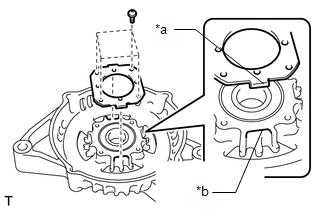
(c) Install the 4 screws.
Torque:
2.3 N·m {23 kgf·cm, 20 in·lbf}
2. INSTALL GENERATOR ROTOR ASSEMBLY
|
(a) Place the generator drive end frame on the generator pulley with clutch. |
|
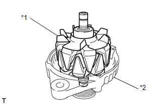
(b) Install the generator rotor assembly to the generator drive end frame.
3. INSTALL GENERATOR COIL ASSEMBLY
|
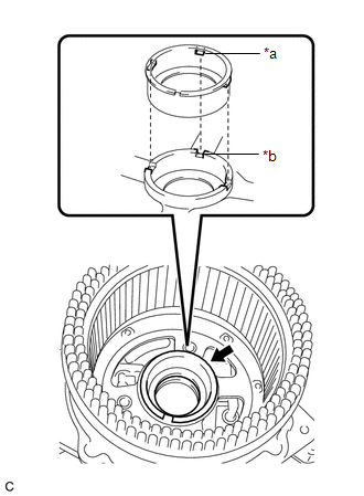
(a) Install a new bearing cover packing. NOTICE: Align the protrusions of the bearing cover packing with the grooves of the generator coil assembly when installing. |
|
|
(b) Using SST and a press, slowly press the generator coil assembly to install it. SST: 09612-70100 09612-07240 |
|
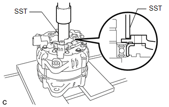
(c) Install the 4 bolts.
Torque:
5.9 N·m {60 kgf·cm, 52 in·lbf}
4. INSTALL GENERATOR BRUSH HOLDER ASSEMBLY
|
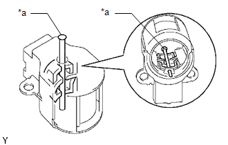
(a) While pushing the 2 brushes into the generator brush holder assembly, insert a 1.0 mm (0.0394 in.) pin into the generator brush holder assembly hole. |
|
|
(b) Install the generator brush holder assembly to the generator coil assembly with the 2 screws. Torque: 1.8 N·m {18 kgf·cm, 16 in·lbf} |
|
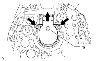
(c) Pull out the pin from the generator brush holder assembly hole.
5. INSTALL GENERATOR TERMINAL INSULATOR
(a) Install the generator terminal insulator to the generator coil assembly.
NOTICE:
Be sure to install the generator terminal insulator in the correct direction.
6. INSTALL GENERATOR REAR END COVER
(a) Install the generator rear end cover to the generator coil assembly with the 3 bolts.
Torque:
4.6 N·m {47 kgf·cm, 41 in·lbf}
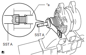
7. INSTALL GENERATOR PULLEY WITH CLUTCH
(a) Secure the generator drive end frame in a vise between aluminum plates.
(b) Temporarily install the generator pulley with clutch to the rotor shaft.
|
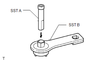
(c) Confirm SST (A) and (B) shown in the illustration. SST: 09820-63021 |
|
|
(d) Place the rotor shaft end into SST (A). |
|
|
(e) Fit SST (B) to the generator pulley with clutch. |
|
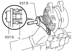
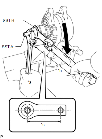
(f) Tighten the generator pulley with clutch by turning SST (B) as shown in the illustration.
|
*a |
Hold |
|
*b |
Torque Wrench Fulcrum Length |
|
*c |
SST Fulcrum Length |
.png) |
Turn |
Torque:
Specified tightening torque :
80 N·m {816 kgf·cm, 59 ft·lbf}
NOTICE:
Be careful as the generator pulley with clutch or rotor shaft may be damaged if the position of SST is not securely maintained while performing this operation.
HINT:
- Calculate the torque wrench reading when changing the fulcrum length
of the torque wrench.
Click here
.gif)
- When using SST (fulcrum length of 100 mm (3.94 in.)) + torque wrench (fulcrum length of 400 mm (15.7 in.)): 64 N*m (653 kgf*cm, 47 ft.*lbf)
(g) Remove SST from the generator pulley with clutch.
(h) Check that the generator pulley with clutch rotates smoothly.
(i) Remove the generator drive end frame from the vise.
8. INSTALL GENERATOR PULLEY CAP
(a) Install a new generator pulley cap to the generator pulley with clutch.
 Installation
INSTALLATION
PROCEDURE
1. INSTALL GENERATOR ASSEMBLY
(a) Install the wire harness clamp bracket to the generator assembly with the
bolt.
Torque:
8.0 N·m {82 kgf·cm, 71 in·lbf}
( ...
 Networking
...
Other materials:
Toyota CH-R Service Manual > Occupant Classification Ecu: On-vehicle Inspection
ON-VEHICLE INSPECTION
CAUTION / NOTICE / HINT
CAUTION:
Be sure to correctly follow the removal and installation procedures for the occupant
detection ECU.
PROCEDURE
1. INSPECT OCCUPANT DETECTION ECU (for Vehicle not Involved in Collision)
(a) Perform a diagnostic system check.
Click here
...
Toyota CH-R Service Manual > Pre-collision System: Diagnostic Trouble Code Chart
DIAGNOSTIC TROUBLE CODE CHART
Pre-collision System
DTC No.
Detection Item
Link
C1A02
Vehicle Information Not Obtained
C1A10
Front Radar Sensor
C1A11
Front ...
Toyota C-HR (AX20) 2023-2026 Owner's Manual
Toyota CH-R Owners Manual
- For safety and security
- Instrument cluster
- Operation of each component
- Driving
- Interior features
- Maintenance and care
- When trouble arises
- Vehicle specifications
- For owners
Toyota CH-R Service Manual
- Introduction
- Maintenance
- Audio / Video
- Cellular Communication
- Navigation / Multi Info Display
- Park Assist / Monitoring
- Brake (front)
- Brake (rear)
- Brake Control / Dynamic Control Systems
- Brake System (other)
- Parking Brake
- Axle And Differential
- Drive Shaft / Propeller Shaft
- K114 Cvt
- 3zr-fae Battery / Charging
- Networking
- Power Distribution
- Power Assist Systems
- Steering Column
- Steering Gear / Linkage
- Alignment / Handling Diagnosis
- Front Suspension
- Rear Suspension
- Tire / Wheel
- Tire Pressure Monitoring
- Door / Hatch
- Exterior Panels / Trim
- Horn
- Lighting (ext)
- Mirror (ext)
- Window / Glass
- Wiper / Washer
- Door Lock
- Heating / Air Conditioning
- Interior Panels / Trim
- Lighting (int)
- Meter / Gauge / Display
- Mirror (int)
- Power Outlets (int)
- Pre-collision
- Seat
- Seat Belt
- Supplemental Restraint Systems
- Theft Deterrent / Keyless Entry

0.008