Toyota CH-R Service Manual: Removal
REMOVAL
CAUTION / NOTICE / HINT
The necessary procedures (adjustment, calibration, initialization, or registration) that must be performed after parts are removed, installed, or replaced during the battery removal/installation are shown below.
Necessary Procedure After Parts Removed/Installed/Replaced|
Replacement Part or Procedure |
Necessary Procedure |
Effect/Inoperative when not Performed |
Link |
|---|---|---|---|
|
Disconnect cable from negative battery terminal |
Initialize back door lock |
Power door lock control system |
|
|
Memorize steering angle neutral point |
Lane departure alert system (w/ Steering Control) |
|
|
|
Pre-collision system |
PROCEDURE
1. PRECAUTION
NOTICE:
After turning the ignition switch off, waiting time may be required before disconnecting the cable from the negative (-) battery terminal. Therefore, make sure to read the disconnecting the cable from the negative (-) battery terminal notices before proceeding with work.
Click here
.gif)
2. DISCONNECT CABLE FROM NEGATIVE BATTERY TERMINAL
|
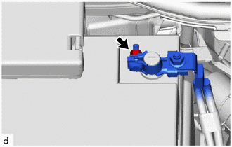
(a) Loosen the nut and disconnect the cable from the negative (-) battery terminal. NOTICE: When disconnecting the cable, some systems need to be initialized after the cable is reconnected. Click here
|
|
3. REMOVE BATTERY
|
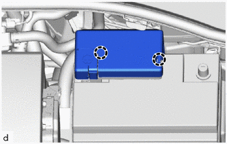
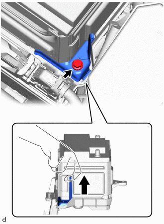
(a) Disengage the 2 claws to remove the fusible link cover. |
|
|
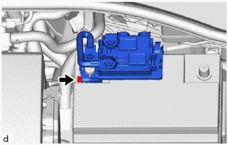
(b) Loosen the nut. |
|
|
(c) Disengage the clamp and disconnect the cable from the positive (+) battery terminal. |
|
|
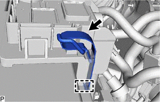
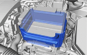
(d) Remove the battery insulator from the battery. |
|
|
(e) Remove the bolt and No. 2 battery clamp. |
|
|
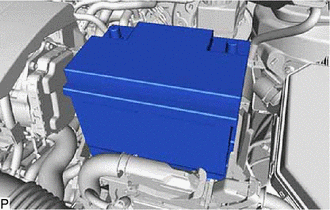
(f) Remove the battery from the vehicle. |
|
 Components
COMPONENTS
ILLUSTRATION
*1
BATTERY
*2
NO. 2 BATTERY CLAMP
*3
POSITIVE BATTERY TERMINAL
*4
NEGATIVE BAT ...
 Installation
INSTALLATION
PROCEDURE
1. INSTALL BATTERY
HINT:
Perform "clear the integrated current value", "switch battery type" after replacing
the battery.
Click here
(a) Inst ...
Other materials:
Toyota CH-R Service Manual > Power Mirror Control System: Power Retractable Mirrors do not Operate with Power Retract Mirror Switch
DESCRIPTION
The outer mirror switch assembly sends a mirror retract/return signal to the
main body ECU (multiplex network body ECU) when the retractable outer mirror switch
on the outer mirror switch assembly is operated. The main body ECU (multiplex network
body ECU) retracts or returns the ...
Toyota CH-R Service Manual > Front Lower Ball Joint: On-vehicle Inspection
ON-VEHICLE INSPECTION
PROCEDURE
1. INSPECT FRONT LOWER BALL JOINT ASSEMBLY
(a) Check for looseness.
(1) Lift up the vehicle.
(2) Move the front lower No. 1 suspension arm sub-assembly up and down
by hand with a force of 294 N (30 kgf) or more to check that there is no
loo ...
Toyota C-HR (AX20) 2023-2026 Owner's Manual
Toyota CH-R Owners Manual
- For safety and security
- Instrument cluster
- Operation of each component
- Driving
- Interior features
- Maintenance and care
- When trouble arises
- Vehicle specifications
- For owners
Toyota CH-R Service Manual
- Introduction
- Maintenance
- Audio / Video
- Cellular Communication
- Navigation / Multi Info Display
- Park Assist / Monitoring
- Brake (front)
- Brake (rear)
- Brake Control / Dynamic Control Systems
- Brake System (other)
- Parking Brake
- Axle And Differential
- Drive Shaft / Propeller Shaft
- K114 Cvt
- 3zr-fae Battery / Charging
- Networking
- Power Distribution
- Power Assist Systems
- Steering Column
- Steering Gear / Linkage
- Alignment / Handling Diagnosis
- Front Suspension
- Rear Suspension
- Tire / Wheel
- Tire Pressure Monitoring
- Door / Hatch
- Exterior Panels / Trim
- Horn
- Lighting (ext)
- Mirror (ext)
- Window / Glass
- Wiper / Washer
- Door Lock
- Heating / Air Conditioning
- Interior Panels / Trim
- Lighting (int)
- Meter / Gauge / Display
- Mirror (int)
- Power Outlets (int)
- Pre-collision
- Seat
- Seat Belt
- Supplemental Restraint Systems
- Theft Deterrent / Keyless Entry

0.0101