Toyota CH-R Service Manual: Transmission Fluid Pressure Sensor/Switch "A" Circuit Low (P0842,P0843)
DESCRIPTION
The ECM performs learning control for the belt clamping pressure based on the belt clamping pressure signal, which is output by the oil pressure sensor.
|
DTC No. |
Detection Item |
DTC Detection Condition |
Trouble Area |
MIL |
Memory |
|---|---|---|---|---|---|
|
P0842 |
Transmission Fluid Pressure Sensor/Switch "A" Circuit Low |
When 2 seconds or more have elapsed after engine start, there is a short in the oil pressure sensor circuit for 0.5 seconds (1 trip detection logic). |
|
Comes on |
DTC stored |
|
P0843 |
Transmission Fluid Pressure Sensor/Switch "A" Circuit High |
When 2 seconds or more have elapsed after engine start, there is an open or a short to +B in the oil pressure sensor circuit for 0.5 seconds (1 trip detection logic). |
|
Comes on |
DTC stored |
MONITOR DESCRIPTION
These DTCs indicate an open or short in the oil pressure sensor circuit. If there is an open or short in the oil pressure sensor circuit, the ECM detects the malfunction, illuminates the MIL and stores a DTC.
MONITOR STRATEGY
|
Related DTCs |
P0842: Oil pressure sensor / Range check (Low voltage) P0843: Oil pressure sensor / Range check (High voltage) |
|
Required sensors/Components |
Oil pressure sensor |
|
Frequency of operation |
Continuous |
|
Duration Conditions |
0.5 seconds |
|
MIL operation |
Immediately |
|
Sequence of operation |
None |
TYPICAL ENABLING CONDITIONS
All|
Starter |
OFF |
|
Time after Starter ON to OFF |
2 seconds or more |
|
Battery voltage |
8 V or more |
|
Time after Battery voltage 8 V or more |
0.5 seconds or more |
|
Write Inhibit |
permit |
|
Time after Write status forbiddance to permit |
0.5 seconds or more |
|
Ignition switch |
ON |
|
Time after Ignition switch OFF to ON |
0.5 seconds or more |
|
Time after Starter ON to OFF |
0.5 seconds or more |
TYPICAL MALFUNCTION THRESHOLDS
P0842:|
Oil pressure sensor output voltage |
Less than 0.28 V |
|
Oil pressure sensor output voltage |
More than 4.9 V |
COMPONENT OPERATING RANGE
|
Oil pressure sensor output voltage |
0.28 to 4.9 V |
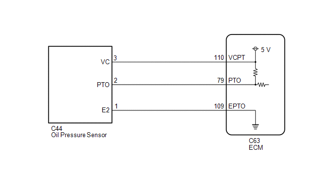
WIRING DIAGRAM
CAUTION / NOTICE / HINT
CAUTION:
.png)
- Do not perform a stall test if there are any people or objects near the vehicle.
- The vehicle could begin moving suddenly, resulting in a serious accident.
.png)
- Do not perform a stall test if any wheel chocks are out of position.
- The vehicle could begin moving suddenly, resulting in a serious accident.
.png)
- Do not perform the stall test on a slippery or low-friction surface that could allow the tires to spin.
- The vehicle could begin moving suddenly, resulting in a serious accident.
NOTICE:
- Perform initialization after replacing any parts related to the continuously
variable transaxle system.
Click here
.gif)
- Check that no DTCs are stored after performing initialization.
Click here
- Perform the universal trip to clear permanent DTCs.
Click here
HINT:
After performing repair, clear the DTCs and perform the following procedure to check that DTCs are not output.
- Start the engine and wait for 2 seconds or more.
- Check for DTCs again.
Click here
PROCEDURE
|
1. |
READ VALUE USING TECHSTREAM (A/T OIL PRESSURE) |
CAUTION:
- Do not perform a stall test if there are any people or objects near the vehicle.
- Do not perform a stall test if any wheel chocks are out of position.
- Do not perform the stall test on a slippery or low-friction surface that could allow the tires to spin.
NOTICE:
- This test must be conducted after checking and confirming that the engine is operating normally.
- Perform this test while the CVT fluid temperature is between 50 and 100°C (122 and 212°F).
- Perform this test with the A/C off.
- Do not perform the stall speed test for longer than 5 seconds.
- Perform this test with the AUTO function (shift-linked function) of the electronic parking brake system off.
(a) Warm up the engine.
(b) Fully apply the parking brake and chock all 4 wheels.
HINT:
When the electric parking brake switch assembly is pulled to the lock side 2 times (2 lock operations), the maximum amount of braking force is applied.
(c) Connect the Techstream to the DLC3.
(d) Turn the ignition switch to ON.
(e) Turn the Techstream on.
(f) Enter the following menus: Powertrain / Engine and ECT / Active Test / Connect the TC and TE1.
Powertrain > Engine and ECT > Active Test|
Tester Display |
|---|
|
Connect the TC and TE1 |
(g) Enter the following menus: Powertrain / Engine and ECT / Data List / Primary.
Powertrain > Engine and ECT > Data List|
Tester Display |
|---|
|
A/T Oil Pressure |
(h) In accordance with the display on the Techstream, read the Data List.
Powertrain > Engine and ECT > Data List|
Tester Display |
Measurement Item |
Range |
Normal Condition |
Diagnostic Note |
|---|---|---|---|---|
|
A/T Oil Pressure |
Secondary oil pressure value |
Min.: -64 MPa Max.: 63.998 MPa |
Secondary oil pressure inspection:
|
- |
|
Result |
Proceed to |
|---|---|
|
Data display is not within Normal Condition range |
A |
|
Data display is within Normal Condition range |
B |
| B | .gif) |
GO TO STEP 6 |
|
.gif)
|
2. |
CHECK HARNESS AND CONNECTOR (OIL PRESSURE SENSOR - ECM) |
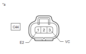
(a) Disconnect the C44 oil pressure sensor connector.
(b) Disconnect the C63 ECM connector.
(c) Measure the resistance according to the value(s) in the table below.
Standard Resistance:
|
Tester Connection |
Condition |
Specified Condition |
|---|---|---|
|
C44-1 (E2) - C63-109 (EPTO) |
Always |
Below 1 Ω |
|
C44-2 (PTO) - C63-79 (PTO) |
Always |
Below 1 Ω |
|
C44-3 (VC) - C63-110 (VCPT) |
Always |
Below 1 Ω |
|
C44-1 (E2) or C63-109 (EPTO) - Body ground and other terminals |
Always |
10 kΩ or higher |
|
C44-2 (PTO) or C63-79 (PTO) - Body ground and other terminals |
Always |
10 kΩ or higher |
|
C44-3 (VC) or C63-110 (VCPT) - Body ground and other terminals |
Always |
10 kΩ or higher |
(d) Measure the voltage according to the value(s) in the table below.
Standard Voltage:
|
Tester Connection |
Switch Condition |
Specified Condition |
|---|---|---|
|
C63-79 (PTO) - Body ground |
Ignition switch ON |
Below 1 V |
|
C44-2 (PTO) - Body ground |
Ignition switch ON |
Below 1 V |
| NG | |
REPAIR OR REPLACE HARNESS OR CONNECTOR (OIL PRESSURE SENSOR - ECM) |
|
|
3. |
CHECK ECM (VCPT TERMINAL VOLTAGE) |
|
(a) Disconnect the oil pressure sensor connector. |
|
(b) Measure the voltage according to the value(s) in the table below.
Standard Voltage:
|
Tester Connection |
Switch Condition |
Specified Condition |
|---|---|---|
|
C44-3 (VC) - C44-1 (E2) |
Ignition switch ON |
4.75 to 5.25 V |
| NG | |
GO TO STEP 5 |
|
|
4. |
REPLACE OIL PRESSURE SENSOR |
(a) Replace the oil pressure sensor.
Click here
| NEXT | |
PERFORM INITIALIZATION |
|
5. |
REPLACE ECM |
(a) Replace the ECM.
Click here
| NEXT | |
PERFORM INITIALIZATION
|
|
6. |
REPLACE ECM |
(a) Replace the ECM.
Click here
| NEXT | |
PERFORM INITIALIZATION
|
 Diagnostic Trouble Code Chart
DIAGNOSTIC TROUBLE CODE CHART
Continuously Variable Transaxle System
DTC No.
Detection Item
MIL
Memory
Link
P0705
T ...
 Transmission Fluid Pressure Sensor/Switch "A" Circuit Range/Performance (P0841,P2829)
DESCRIPTION
The ECM controls the secondary oil pressure based on the secondary oil pressure
signal output by the oil pressure sensor.
DTC No.
Detection Item
DTC De ...
Other materials:
Toyota CH-R Service Manual > Smart Key System(for Start Function): Engine does not Start
DESCRIPTION
When the electrical key transmitter sub-assembly is in the cabin and the engine
switch is pressed, the certification ECU (smart key ECU assembly) receives a signal
and changes the power source mode. Additionally, when the shift lever is in P and
the brake pedal is depressed, the e ...
Toyota CH-R Service Manual > Pre-collision System: Utility
UTILITY
NOTICE:
When replacing a millimeter wave radar sensor assembly, replace it with a new
one.
If the millimeter wave radar sensor assembly has been replaced or removed/installed,
be sure to perform Front Beam Axis Adjustment. If not performed, DTC C1A14 will
be stored when the system i ...
Toyota CH-R Owners Manual
- For safety and security
- Instrument cluster
- Operation of each component
- Driving
- Interior features
- Maintenance and care
- When trouble arises
- Vehicle specifications
- For owners
Toyota CH-R Service Manual
- Introduction
- Maintenance
- Audio / Video
- Cellular Communication
- Navigation / Multi Info Display
- Park Assist / Monitoring
- Brake (front)
- Brake (rear)
- Brake Control / Dynamic Control Systems
- Brake System (other)
- Parking Brake
- Axle And Differential
- Drive Shaft / Propeller Shaft
- K114 Cvt
- 3zr-fae Battery / Charging
- Networking
- Power Distribution
- Power Assist Systems
- Steering Column
- Steering Gear / Linkage
- Alignment / Handling Diagnosis
- Front Suspension
- Rear Suspension
- Tire / Wheel
- Tire Pressure Monitoring
- Door / Hatch
- Exterior Panels / Trim
- Horn
- Lighting (ext)
- Mirror (ext)
- Window / Glass
- Wiper / Washer
- Door Lock
- Heating / Air Conditioning
- Interior Panels / Trim
- Lighting (int)
- Meter / Gauge / Display
- Mirror (int)
- Power Outlets (int)
- Pre-collision
- Seat
- Seat Belt
- Supplemental Restraint Systems
- Theft Deterrent / Keyless Entry

0.0231