Toyota CH-R Service Manual: Engine does not Start
DESCRIPTION
When the electrical key transmitter sub-assembly is in the cabin and the engine switch is pressed, the certification ECU (smart key ECU assembly) receives a signal and changes the power source mode. Additionally, when the shift lever is in P and the brake pedal is depressed, the engine can be started by pressing the engine switch. If the steering is unlocked, the engine can also be started by pressing the engine switch with the shift lever in N and the brake pedal depressed.
Related Data List and Active Test Items|
Problem Symptom |
Data List and Active Test |
|---|---|
|
Engine does not start |
Power Source Control
Smart Key
Starting Control
|
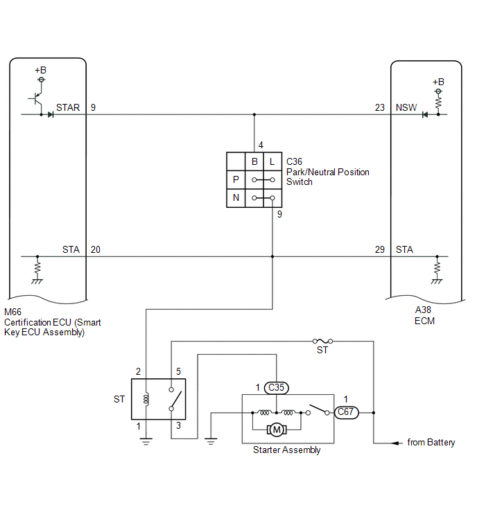
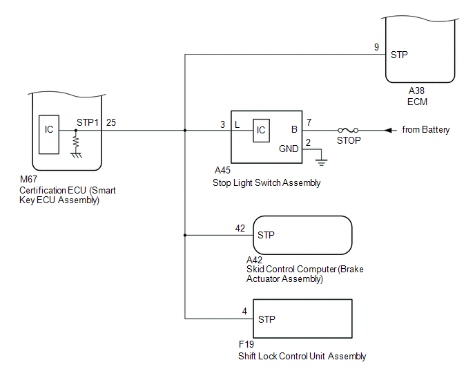
WIRING DIAGRAM
CAUTION / NOTICE / HINT
NOTICE:
- When using the Techstream with the engine switch off, connect the Techstream to the DLC3 and turn a courtesy light switch on and off at intervals of 1.5 seconds or less until communication between the Techstream and the vehicle begins. Then select the vehicle type under manual mode and enter the following menus: Body Electrical / Smart Key. While using the Techstream, periodically turn a courtesy light switch on and off at intervals of 1.5 seconds or less to maintain communication between the Techstream and the vehicle.
- The smart key system (for Start Function) uses the LIN communication
system and CAN communication system. Inspect the communication function
by following How to Proceed with Troubleshooting. Troubleshoot the smart
key system (for Start Function) after confirming that the communication
systems are functioning properly.
Click here
.gif)
- If the smart key system (for Start Function) has been canceled, enable
the system before performing troubleshooting.
Click here
- Inspect the fuses of circuits related to this system before performing the following procedure.
- Before replacing the certification ECU (smart key ECU assembly) or an
electrical key transmitter sub-assembly, refer to smart key system (for
Start Function) Precaution.
Click here
- After completing repairs, confirm that the problem does not recur.
HINT:
- When the cable is disconnected and reconnected to the negative (-) battery terminal, the power source mode returns to the state it was in before the cable was disconnected.
- If the engine switch is turned from on (IG) to on (ACC) with the shift lever in any position other than P, and then the shift lever is moved to P and the engine switch is pressed with the brake pedal depressed, the engine switch will turn off.
- If the brake pedal is repeatedly depressed while the engine is stopped, the brake booster pressure will be released and the force required to depress the brake pedal to illuminate the stop lights will increase.
- The certification ECU (smart key ECU assembly) stores the operation history of smart key system and it can be read using the Techstream.
|
Tester Display |
|---|
|
Operation History |
|
Parameter Name |
Content |
|---|---|
|
Operating Engine Switch / Key RF Signal Interference |
When the engine switch was operated, the electrical key transmitter sub-assembly could not be confirmed due to wave interference. |
PROCEDURE
|
1. |
CHECK ELECTRICAL KEY TRANSMITTER SUB-ASSEMBLY |
(a) Press a switch of the electrical key transmitter sub-assembly.
OK:
The electrical key transmitter sub-assembly LED illuminates.
| NG | .gif) |
GO TO STEP 14 |
|
.gif)
|
2. |
READ VALUE USING TECHSTREAM (KEY LOW BATTERY) |
(a) Connect the Techstream to the DLC3.
(b) Turn the engine switch on (IG).
(c) Turn the Techstream on.
(d) Enter the following menus: Body Electrical / Smart Key / Data List.
(e) Read the Data List according to the display on the Techstream.
Body Electrical > Smart Key > Data List|
Tester Display |
Measurement Item |
Range |
Normal Condition |
Diagnostic Note |
|---|---|---|---|---|
|
Key Low Battery |
Transmitter battery depleted |
No or Yes |
No: Transmitter battery not depleted Yes: Transmitter battery depleted |
The electrical key transmitter sub-assembly sends voltage information to the certification ECU (smart key ECU assembly) when it is transmitting. "Yes" is displayed for the Data List item "Key Low Battery" when this voltage information indicates 2.2 V or less. This Data List item should be checked when the electrical key transmitter sub-assembly is at room temperature (example: at -20°C (-4°F), "Yes" may be displayed even if the transmitter battery is new). |
|
Tester Display |
|---|
|
Key Low Battery |
|
Result |
Proceed to |
|---|---|
|
"No" is displayed on the Techstream screen |
A |
|
"Yes" is displayed on the Techstream screen |
B |
| B | |
REPLACE TRANSMITTER BATTERY |
|
|
3. |
CHECK ENGINE CRANK |
(a) Get into the vehicle while carrying the electrical key transmitter.
(b) Move the shift lever to P.
(c) Depress the brake pedal.
(d) Press the engine switch and check that the engine cranks.
|
Result |
Proceed to |
|---|---|
|
Engine cranks, but there is no initial combustion or engine is difficult to start |
A |
|
Engine does not cranks |
B |
| B | |
GO TO STEP 6 |
|
|
4. |
CHECK HARNESS AND CONNECTOR (CERTIFICATION ECU (SMART KEY ECU ASSEMBLY) - ECM) |
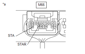
(a) Disconnect the M66 certification ECU (smart key ECU assembly) connector.
(b) Disconnect the A38 ECM connector.
(c) Disconnect the C36 park/neutral position switch connector.
(d) Remove the ST relay.
(e) Measure the resistance according to the value(s) in the table below.
Standard Resistance:
|
Tester Connection |
Condition |
Specified Condition |
|---|---|---|
|
M66-20 (STA) - A38-29 (STA) |
Always |
Below 1 Ω |
|
M66-20 (STA) or A38-29 (STA) - Body ground |
Always |
10 kΩ or higher |
| NG | |
REPAIR OR REPLACE HARNESS OR CONNECTOR |
|
|
5. |
CHECK CONNECTOR CONNECTION CONDITION |
(a) Disconnect the M66 certification ECU (smart key ECU assembly) connector.
(b) Connect the M66 certification ECU (smart key ECU assembly) connector.
(c) Press the engine switch and check that the engine starts.
OK:
Engine starts.
| OK | |
CONNECT SECURELY |
| NG | |
GO TO IMMOBILISER SYSTEM |
|
6. |
CHECK FOR DTC |
(a) Using the Techstream, check for certification ECU (smart key ECU assembly) DTCs.
Body Electrical > Smart Key > Trouble Codes Body Electrical > Starting Control > Trouble Codes Body Electrical > Power Source Control > Trouble Codes|
Result |
Proceed to |
|---|---|
|
DTCs are not output |
A |
|
Smart key system (for Start Function) DTCs are output |
B |
| B | |
GO TO DIAGNOSTIC TROUBLE CODE CHART |
|
|
7. |
CHECK ENGINE SWITCH CONDITION |
(a) Get into the vehicle while carrying an electrical key transmitter sub-assembly.
(b) Move the shift lever to P.
(c) With the brake pedal released, check that pressing the engine switch causes the power source mode to change.
|
Result |
Proceed to |
|---|---|
|
Power source mode changes : Off → on (ACC) → on (IG) → off |
A |
|
Power source mode does not change to on (ACC) or on (IG) |
B |
|
Power source mode changes to on (IG) but not to on (ACC) |
C |
|
Power source mode changes to on (ACC) but not to on (IG) |
D |
| B | |
GO TO POWER SOURCE MODE DOES NOT CHANGE TO ON (IG AND ACC)
|
| C | |
GO TO POWER SOURCE MODE DOES NOT CHANGE TO ON (ACC) |
| D | |
GO TO POWER SOURCE MODE DOES NOT CHANGE TO ON (IG) |
|
|
8. |
READ VALUE USING TECHSTREAM (STOP LIGHT SWITCH1) |
(a) Connect the Techstream to the DLC3.
(b) Turn the engine switch on (IG).
(c) Turn the Techstream on.
(d) Enter the following menus: Body Electrical / Power Source Control / Data List.
(e) According to the display on the Techstream, read the Data List.
Body Electrical > Power Source Control > Data List|
Tester Display |
Measurement Item |
Range |
Normal Condition |
Diagnostic Note |
|---|---|---|---|---|
|
Stop Light Switch1 |
State of brake pedal |
OFF or ON |
OFF: Brake pedal released ON: Brake pedal depressed |
|
|
Tester Display |
|---|
|
Stop Light Switch1 |
OK:
The item in the Data List changes when the brake pedal is depressed and released.
| NG | |
GO TO STEP 28 |
|
|
9. |
READ VALUE USING TECHSTREAM (NEUTRAL SW/ CLUTCH SW, SHIFT POSITION P OR N) |
(a) Connect the Techstream to the DLC3.
(b) Turn the engine switch on (IG).
(c) Turn the Techstream on.
(d) Enter the following menus: Body Electrical / Power Source Control or Starting Control / Data List.
(e) According to the display on the Techstream, read the Data List.
Body Electrical > Power Source Control > Data List|
Tester Display |
Measurement Item |
Range |
Normal Condition |
Diagnostic Note |
|---|---|---|---|---|
|
Neutral SW/ Clutch SW |
Shift position (P and N) |
OFF or ON |
OFF: Shift lever not in P or N ON: Shift lever in P or N |
|
|
Tester Display |
|---|
|
Neutral SW/ Clutch SW |
|
Tester Display |
Measurement Item |
Range |
Normal Condition |
Diagnostic Note |
|---|---|---|---|---|
|
Shift Position P or N |
Park/neutral position switch status |
OFF or ON |
OFF: Shift lever in any position other than P or N ON: Shift lever in P or N |
When OFF is displayed, the engine will not crank. |
|
Tester Display |
|---|
|
Shift Position P or N |
OK:
The item in the Data List changes according to the shift position.
| NG | |
GO TO STEP 26 |
|
|
10. |
READ VALUE USING TECHSTREAM (STARTER REQUEST SIGNAL) |
(a) Connect the Techstream to the DLC3.
(b) Turn the engine switch on (IG).
(c) Turn the Techstream on.
(d) Enter the following menus: Body Electrical / Power Source Control / Data List.
(e) According to the display on the Techstream, read the Data List.
Body Electrical > Power Source Control > Data List|
Tester Display |
Measurement Item |
Range |
Normal Condition |
Diagnostic Note |
|---|---|---|---|---|
|
Starter Request Signal |
Engine start request signal status |
OFF or ON |
OFF: The engine switch is not pressed ON: With the shift lever in P and the brake pedal depressed, the engine switch is pressed and held |
|
|
Tester Display |
|---|
|
Starter Request Signal |
NOTICE:
Check that the key warning light is illuminated in green on the combination meter assembly, and then press the engine switch.
OK:
The display changes in response to the operation of the engine switch.
| NG | |
GO TO STEP 24 |
|
|
11. |
READ VALUE USING TECHSTREAM (STARTER SW) |
(a) Connect the Techstream to the DLC3.
(b) Turn the engine switch on (IG).
(c) Turn the Techstream on.
(d) Enter the following menus: Body Electrical / Starting Control / Data List.
(e) Get into the vehicle while carrying the electrical key transmitter sub-assembly, move the shift lever to P, press the engine switch while depressing the brake pedal and confirm that the Data List item changes.
Body Electrical > Starting Control > Data List|
Tester Display |
Measurement Item |
Range |
Normal Condition |
Diagnostic Note |
|---|---|---|---|---|
|
Starter SW |
Starter operation request |
OFF or ON |
OFF: Starter operation not requested ON: Starter operation requested |
When OFF is displayed, the engine will not crank. |
|
Tester Display |
|---|
|
Starter SW |
OK:
The Data List item changes.
| NG | |
REPLACE CERTIFICATION ECU (SMART KEY ECU ASSEMBLY) |
|
|
12. |
READ VALUE USING TECHSTREAM (STARTER RELAY) |
(a) Connect the Techstream to the DLC3.
(b) Turn the engine switch on (IG).
(c) Turn the Techstream on.
(d) Enter the following menus: Body Electrical / Starting Control / Data List.
(e) According to the display on the Techstream, read the Data List.
Body Electrical > Starting Control > Data List|
Tester Display |
Measurement Item |
Range |
Normal Condition |
Diagnostic Note |
|---|---|---|---|---|
|
Starter Relay |
Starter relay voltage monitor |
OFF or ON |
OFF: ST relay off ON: ST relay on |
When OFF is displayed the engine cannot be cranked. |
|
Tester Display |
|---|
|
Starter Relay |
| NG | |
GO TO STEP 15 |
|
|
13. |
CHECK CONNECTOR CONNECTION CONDITION |
(a) Disconnect the M66 certification ECU (smart key ECU assembly) connector.
(b) Connect the M66 certification ECU (smart key ECU assembly) connector.
(c) Press the engine switch and check that the engine starts.
OK:
Engine starts.
| OK | |
CONNECT SECURELY |
| NG | |
REPLACE CERTIFICATION ECU (SMART KEY ECU ASSEMBLY) |
|
14. |
INSPECT TRANSMITTER BATTERY |
(a) Inspect the transmitter battery.
Click here
NOTICE:
Do not wrap the lead wire ground a terminal, wedge it between terminals, or solder it. The terminal may be deformed or damaged, and the transmitter battery will not be able to be installed correctly.
| OK | |
REPLACE ELECTRICAL KEY TRANSMITTER SUB-ASSEMBLY |
| NG | |
REPLACE TRANSMITTER BATTERY |
|
15. |
INSPECT ST RELAY |
(a) Remove the ST relay.
(b) Inspect the ST relay.
Click here
| NG | |
REPLACE ST RELAY |
|
|
16. |
CHECK HARNESS AND CONNECTOR (CERTIFICATION ECU (SMART KEY ECU ASSEMBLY) - BODY GROUND) |
|
(a) Disconnect the M66 certification ECU (smart key ECU assembly) connector. |
|
(b) Disconnect the A38 ECM connector.
(c) Move the shift lever to P or N.
(d) Measure the resistance according to the value(s) in the table below.
Standard Resistance:
|
Tester Connection |
Condition |
Specified Condition |
|---|---|---|
|
M66-20 (STA) - Body ground |
20°C (68°F) |
101.69 to 153.84 Ω |
|
M66-9 (STAR) - Body ground |
| NG | |
GO TO STEP 19 |
|
|
17. |
INSPECT STARTER ASSEMBLY |
(a) Remove the starter assembly.
Click here
(b) Inspect the starter assembly.
Click here
| NG | |
REPLACE STARTER ASSEMBLY |
|
|
18. |
CHECK HARNESS AND CONNECTOR (BATTERY - STARTER AND ST RELAY) |
(a) Remove the starter assembly from the vehicle to perform an inspection.
Click here
(b) Remove the ST relay.
(c) Measure the voltage according to the value(s) in the table below.
Standard Voltage:
|
Tester Connection |
Condition |
Specified Condition |
|---|---|---|
|
C67-1 - Body ground |
Always |
11 to 14 V |
|
ST relay terminal 5 - Body ground |
Always |
11 to 14 V |
(d) Measure the resistance according to the value(s) in the table below.
Standard Resistance:
|
Tester Connection |
Condition |
Specified Condition |
|---|---|---|
|
ST relay terminal 3 - C35-1 |
Always |
Below 1 Ω |
|
ST relay terminal 3 or C35-1 - Body ground |
Always |
10 kΩ or higher |
| OK | |
REPLACE CERTIFICATION ECU (SMART KEY ECU ASSEMBLY) |
| NG | |
REPAIR OR REPLACE HARNESS OR CONNECTOR |
|
19. |
CHECK HARNESS AND CONNECTOR (CERTIFICATION ECU (SMART KEY ECU ASSEMBLY) - PARK/NEUTRAL POSITION SWITCH) |
(a) Disconnect the M66 certification ECU (smart key ECU assembly) connector.
(b) Disconnect the C36 park/neutral position switch connector.
(c) Disconnect the A38 ECM connector.
(d) Measure the resistance according to the value(s) in the table below.
Standard Resistance:
|
Tester Connection |
Condition |
Specified Condition |
|---|---|---|
|
M66-9 (STAR) - C36-4 (B) |
Always |
Below 1 Ω |
|
M66-9 (STAR) or C36-4 (B) |
Always |
10 kΩ or higher |
| NG | |
REPAIR OR REPLACE HARNESS OR CONNECTOR |
|
|
20. |
CHECK HARNESS AND CONNECTOR (PARK/NEUTRAL POSITION SWITCH - ST RELAY) |
(a) Disconnect the C36 park/neutral position switch connector.
(b) Remove the ST relay.
(c) Disconnect the M66 certification ECU (smart key ECU assembly) connector.
(d) Disconnect the A38 ECM connector.
(e) Measure the resistance according to the value(s) in the table below.
Standard Resistance:
|
Tester Connection |
Condition |
Specified Condition |
|---|---|---|
|
C36-9 (L) - ST relay terminal 2 |
Always |
Below 1 Ω |
|
C36-9 (L) or ST relay terminal 2 - Body ground |
Always |
10 kΩ or higher |
| NG | |
REPAIR OR REPLACE HARNESS OR CONNECTOR |
|
|
21. |
CHECK HARNESS AND CONNECTOR (CERTIFICATION ECU (SMART KEY ECU ASSEMBLY) - ST RELAY) |
(a) Disconnect the M66 certification ECU (smart key ECU assembly) connector.
(b) Disconnect the A38 ECM connector.
(c) Disconnect the C36 park/neutral position switch connector.
(d) Remove the ST relay.
(e) Measure the resistance according to the value(s) in the table below.
Standard Resistance:
|
Tester Connection |
Condition |
Specified Condition |
|---|---|---|
|
M66-20 (STA) - ST relay terminal 2 |
Always |
Below 1 Ω |
|
M66-20 (STA) or ST relay terminal 2 - Body ground |
Always |
10 kΩ or higher |
| NG | |
REPAIR OR REPLACE HARNESS OR CONNECTOR |
|
|
22. |
CHECK HARNESS AND CONNECTOR (ST RELAY - BODY GROUND) |
(a) Remove the ST relay.
(b) Measure the resistance according to the value(s) in the table below.
Standard Resistance:
|
Tester Connection |
Condition |
Specified Condition |
|---|---|---|
|
ST relay terminal 1 - Body ground |
Always |
Below 1 Ω |
| NG | |
REPAIR OR REPLACE HARNESS OR CONNECTOR |
|
|
23. |
CHECK CONNECTOR CONNECTION CONDITION |
(a) Disconnect the M66 certification ECU (smart key ECU assembly) connector.
(b) Connect the M66 certification ECU (smart key ECU assembly) connector.
(c) Press the engine switch and check that the engine starts.
OK:
Engine starts.
| OK | |
CONNECT SECURELY |
| NG | |
REPLACE CERTIFICATION ECU (SMART KEY ECU ASSEMBLY) |
|
24. |
CHECK STEERING LOCK SYSTEM |
(a) Check that the steering unlocks when the engine switch is turned on (ACC).
OK:
The steering unlocks.
| NG | |
GO TO STEERING LOCK SYSTEM (PROBLEM SYMPTOMS TABLE) |
|
|
25. |
CHECK SECURITY INDICATOR LIGHT (IMMOBILISER SYSTEM UNSET) |
(a) Get into the vehicle while carrying an electrical key transmitter sub-assembly.
(b) Move the shift lever to P.
(c) Press the engine switch with the brake pedal released and check that the security indicator light changes from blinking to off at the same time that the power source mode changes to on (ACC).
HINT:
It is determined that the immobiliser function is operating correctly if the security indicator light changes from blinking to off at the same time that the power source mode changes to on (ACC).
OK:
Security indicator light changes from blinking to off at the same time that the power source mode changes to on (ACC).
| OK | |
REPLACE CERTIFICATION ECU (SMART KEY ECU ASSEMBLY) |
| NG | |
GO TO IMMOBILISER SYSTEM (PROBLEM SYMPTOMS TABLE)
|
|
26. |
INSPECT PARK/NEUTRAL POSITION SWITCH |
(a) Remove the park/neutral position switch.
Click here
(b) Inspect the park/neutral position switch.
Click here
| NG | |
REPLACE PARK/NEUTRAL POSITION SWITCH |
|
|
27. |
CHECK HARNESS AND CONNECTOR (CERTIFICATION ECU (SMART KEY ECU ASSEMBLY) - PARK/NEUTRAL POSITION SWITCH) |
(a) Disconnect the M66 certification ECU (smart key ECU assembly) connector.
(b) Disconnect the C36 park/neutral position switch connector.
(c) Disconnect the A38 ECM connector.
(d) Measure the resistance according to the value(s) in the table below.
Standard Resistance:
|
Tester Connection |
Condition |
Specified Condition |
|---|---|---|
|
M66-9 (STAR) - C36-4 (B) |
Always |
Below 1 Ω |
|
M66-9 (STAR) or C36-4 (B) |
Always |
10 kΩ or higher |
| OK | |
REPLACE CERTIFICATION ECU (SMART KEY ECU ASSEMBLY) |
| NG | |
REPAIR OR REPLACE HARNESS OR CONNECTOR |
|
28. |
INSPECT STOP LIGHT SWITCH ASSEMBLY |
(a) Remove the stop light switch assembly.
Click here
(b) Inspect the stop light switch assembly.
Click here
| NG | |
REPLACE STOP LIGHT SWITCH ASSEMBLY |
|
|
29. |
CHECK HARNESS AND CONNECTOR (STOP LIGHT SWITCH ASSEMBLY - POWER SUPPLY AND BODY GROUND) |
|
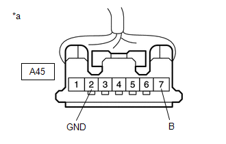
(a) Disconnect the stop light switch assembly connector. |
|
(b) Measure the voltage according to the value(s) in the table below.
Standard Voltage:
|
Tester Connection |
Condition |
Specified Condition |
|---|---|---|
|
A45-7 (B) - Body ground |
Always |
11 to 14 V |
(c) Measure the resistance according to the value(s) in the table below.
Standard Resistance:
|
Tester Connection |
Condition |
Specified Condition |
|---|---|---|
|
A45-2 (GND) - Body ground |
Always |
Below 1 Ω |
| NG | |
REPAIR OR REPLACE HARNESS OR CONNECTOR |
|
|
30. |
CHECK HARNESS AND CONNECTOR (CERTIFICATION ECU (SMART KEY ECU ASSEMBLY) - STOP LIGHT SWITCH ASSEMBLY) |
(a) Disconnect the M67 certification ECU (smart key ECU assembly) connector.
(b) Disconnect the A38 ECM connector.
(c) Disconnect the A42 skid control computer (brake actuator assembly) connector.
(d) Disconnect the F19 shift lock control unit assembly connector.
(e) Measure the resistance according to the value(s) in the table below.
Standard Resistance:
|
Tester Connection |
Condition |
Specified Condition |
|---|---|---|
|
M67-25 (STP1) - A45-3 (L) |
Always |
Below 1 Ω |
|
M67-25 (STP1) or A45-3 (L) - Body ground |
Always |
10 kΩ or higher |
| OK | |
REPLACE CERTIFICATION ECU (SMART KEY ECU ASSEMBLY) |
| NG | |
REPAIR OR REPLACE HARNESS OR CONNECTOR |
 Runnable Signal Malfunction (B2286,P0335)
DESCRIPTION
These DTCs are stored when the engine speed signal sent by the ECM via direct
line and the engine speed signal sent via CAN communication do not match.
DTC No.
De ...
 Power Source Mode does not Change to ON (IG and ACC)
DESCRIPTION
If any of the following operations are performed, the certification ECU (smart
key ECU assembly) receives a signal, and changes the power source mode.
With the electrical key tr ...
Other materials:
Toyota CH-R Service Manual > Lin Communication System: Parts Location
PARTS LOCATION
ILLUSTRATION
*A
w/ Double Locking System
-
-
*1
NO. 1 ENGINE ROOM RELAY BLOCK
- DOOR DBL/L FUSE
-
-
ILLUSTRATION
*A
w/ Smart Key System
*B ...
Toyota CH-R Service Manual > Audio And Visual System(for Radio And Display Type): Air Conditioner ECU Vehicle Information Reading/Writing Processor Malfunction
(B15F5)
DESCRIPTION
This DTC is stored when items controlled by the air conditioning amplifier assembly
cannot be customized via the audio and visual system vehicle customization screen.
HINT:
The air conditioning amplifier assembly controls the air conditioning system
related items that are customiz ...
Toyota C-HR (AX20) 2023-2026 Owner's Manual
Toyota CH-R Owners Manual
- For safety and security
- Instrument cluster
- Operation of each component
- Driving
- Interior features
- Maintenance and care
- When trouble arises
- Vehicle specifications
- For owners
Toyota CH-R Service Manual
- Introduction
- Maintenance
- Audio / Video
- Cellular Communication
- Navigation / Multi Info Display
- Park Assist / Monitoring
- Brake (front)
- Brake (rear)
- Brake Control / Dynamic Control Systems
- Brake System (other)
- Parking Brake
- Axle And Differential
- Drive Shaft / Propeller Shaft
- K114 Cvt
- 3zr-fae Battery / Charging
- Networking
- Power Distribution
- Power Assist Systems
- Steering Column
- Steering Gear / Linkage
- Alignment / Handling Diagnosis
- Front Suspension
- Rear Suspension
- Tire / Wheel
- Tire Pressure Monitoring
- Door / Hatch
- Exterior Panels / Trim
- Horn
- Lighting (ext)
- Mirror (ext)
- Window / Glass
- Wiper / Washer
- Door Lock
- Heating / Air Conditioning
- Interior Panels / Trim
- Lighting (int)
- Meter / Gauge / Display
- Mirror (int)
- Power Outlets (int)
- Pre-collision
- Seat
- Seat Belt
- Supplemental Restraint Systems
- Theft Deterrent / Keyless Entry

0.0083