Toyota CH-R Service Manual: Double Locking ECU Communication Stop (B1249)
DESCRIPTION
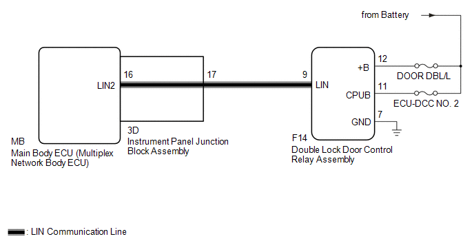
The main body ECU (multiplex network body ECU) stores this DTC when communication with the double lock door control relay assembly stops for 10 seconds or more.
|
DTC No. |
Detection Item |
DTC Detection Condition |
Trouble Area |
|---|---|---|---|
|
B1249 |
Double Locking ECU Communication Stop |
No communication between double lock door control relay assembly and main body ECU (multiplex network body ECU) for 10 seconds or more |
|
WIRING DIAGRAM
CAUTION / NOTICE / HINT
NOTICE:
- Inspect the fuses for circuits related to this system before performing the following procedure.
- If the main body ECU (multiplex network body ECU) is replaced, refer
to Registration.*1
Click here
.gif)
- *1: w/ Smart Key System
PROCEDURE
|
1. |
INSPECT INSTRUMENT PANEL JUNCTION BLOCK ASSEMBLY |
(a) Remove the instrument panel junction block assembly.
Click here
|
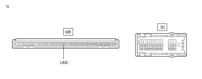
*a |
Component without harness connected (Instrument Panel Junction Block Assembly) |
- |
- |
(b) Remove the main body ECU (multiplex network body ECU) from the instrument panel junction block assembly.
(c) Measure the resistance according to the value(s) in the table below.
HINT:
This inspection is to check the LIN communication line in the instrument panel junction block assembly that connects the wire harness to the built-in main body ECU (multiplex network body ECU).
Standard Resistance:
|
Tester Connection |
Condition |
Specified Condition |
|---|---|---|
|
3D-17 - MB-16 (LIN2) |
Always |
Below 1 Ω |
| NG | .gif) |
REPLACE INSTRUMENT PANEL JUNCTION BLOCK ASSEMBLY |
|
.gif)
|
2. |
CHECK HARNESS AND CONNECTOR (MAIN BODY ECU (MULTIPLEX NETWORK BODY ECU) - DOUBLE LOCK DOOR CONTROL RELAY ASSEMBLY) |
(a) Disconnect the F14 double lock door control relay assembly connector.
(b) Measure the resistance according to the value(s) in the table below.
NOTICE:
Make sure that each ECU is in sleep mode before performing the inspection. To enter sleep mode, turn the ignition switch from ON to off and wait for 180 seconds or more without operating any switches.
Standard Resistance:
|
Tester Connection |
Switch Condition |
Specified Condition |
|---|---|---|
|
3D-17 - F14-9 (LIN) |
Ignition switch off |
Below 1 Ω |
|
F14-9 (LIN) or 3D-17 - Body ground |
Ignition switch off |
10 kΩ or higher |
| NG | |
REPAIR OR REPLACE HARNESS OR CONNECTOR |
|
|
3. |
CHECK HARNESS AND CONNECTOR (DOUBLE LOCK DOOR CONTROL RELAY ASSEMBLY - BATTERY, BODY GROUND) |
(a) Measure the voltage according to the value(s) in the table below.
Standard Voltage:
|
Tester Connection |
Condition |
Specified Condition |
|---|---|---|
|
F14-12 (+B) - F14-7 (GND) |
Always |
11 to 14 V |
|
F14-11 (CPUB) - F14-7 (GND) |
Always |
11 to 14 V |
(b) Measure the resistance according to the value(s) in the table below.
Standard Resistance:
|
Tester Connection |
Condition |
Specified Condition |
|---|---|---|
|
F14-7 (GND) - Body ground |
Always |
Below 1 Ω |
| NG | |
REPAIR OR REPLACE HARNESS OR CONNECTOR |
|
|
4. |
REPLACE DOUBLE LOCK DOOR CONTROL RELAY ASSEMBLY |
(a) Replace the double lock door control relay assembly.
Click here
|
|
5. |
CHECK FOR DTC |
(a) Clear the DTCs.
Click here
(b) Recheck for DTCs.
Body Electrical > Main Body > Trouble CodesOK:
DTC B1249 is not output.
| OK | |
END (DOUBLE LOCK DOOR CONTROL RELAY ASSEMBLY WAS DEFECTIVE) |
| NG | |
REPLACE MAIN BODY ECU (MULTIPLEX NETWORK BODY ECU) |
 Driver Side Door ECU Communication Stop (B2321)
DESCRIPTION
This DTC is stored when LIN communication between the power window regulator
motor assembly (for driver door) and main body ECU (multiplex network body ECU)
stops for 10 seconds or mo ...
 LIN Communication Bus Malfunction (B2325)
DESCRIPTION
If the main body ECU (multiplex network body ECU) detects a communication error
with an ECU connected to the door bus lines for 7 seconds or more, DTC B2325 will
be stored.
...
Other materials:
Toyota CH-R Service Manual > Rear Suspension Member: Removal
REMOVAL
CAUTION / NOTICE / HINT
The necessary procedures (adjustment, calibration, initialization, or registration)
that must be performed after parts are removed and installed, or replaced during
rear suspension member sub-assembly removal/installation are shown below.
Necessary Procedures A ...
Toyota CH-R Service Manual > Rear Wiper Motor: Installation
INSTALLATION
PROCEDURE
1. INSTALL REAR WIPER MOTOR ASSEMBLY
(a) Install the rear wiper motor assembly with the 3 bolts.
Torque:
5.5 N·m {56 kgf·cm, 49 in·lbf}
(b) Connect the connector.
2. INSTALL REAR WIPER MOTOR GROMMET
(a) Apply MP grease to the entire surface of the rear w ...
Toyota C-HR (AX20) 2023-2026 Owner's Manual
Toyota CH-R Owners Manual
- For safety and security
- Instrument cluster
- Operation of each component
- Driving
- Interior features
- Maintenance and care
- When trouble arises
- Vehicle specifications
- For owners
Toyota CH-R Service Manual
- Introduction
- Maintenance
- Audio / Video
- Cellular Communication
- Navigation / Multi Info Display
- Park Assist / Monitoring
- Brake (front)
- Brake (rear)
- Brake Control / Dynamic Control Systems
- Brake System (other)
- Parking Brake
- Axle And Differential
- Drive Shaft / Propeller Shaft
- K114 Cvt
- 3zr-fae Battery / Charging
- Networking
- Power Distribution
- Power Assist Systems
- Steering Column
- Steering Gear / Linkage
- Alignment / Handling Diagnosis
- Front Suspension
- Rear Suspension
- Tire / Wheel
- Tire Pressure Monitoring
- Door / Hatch
- Exterior Panels / Trim
- Horn
- Lighting (ext)
- Mirror (ext)
- Window / Glass
- Wiper / Washer
- Door Lock
- Heating / Air Conditioning
- Interior Panels / Trim
- Lighting (int)
- Meter / Gauge / Display
- Mirror (int)
- Power Outlets (int)
- Pre-collision
- Seat
- Seat Belt
- Supplemental Restraint Systems
- Theft Deterrent / Keyless Entry

0.0066