Toyota CH-R Service Manual: System Diagram
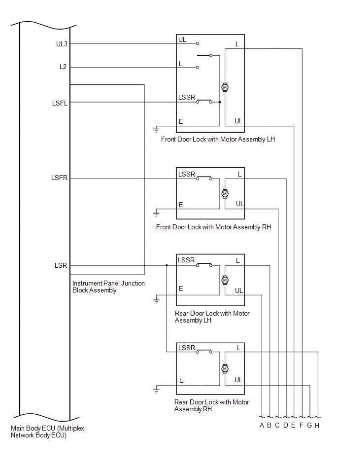
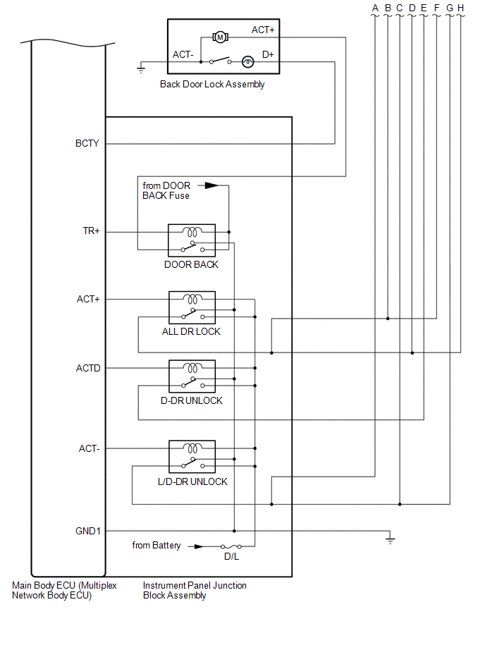
SYSTEM DIAGRAM
Wireless Door Lock Control System
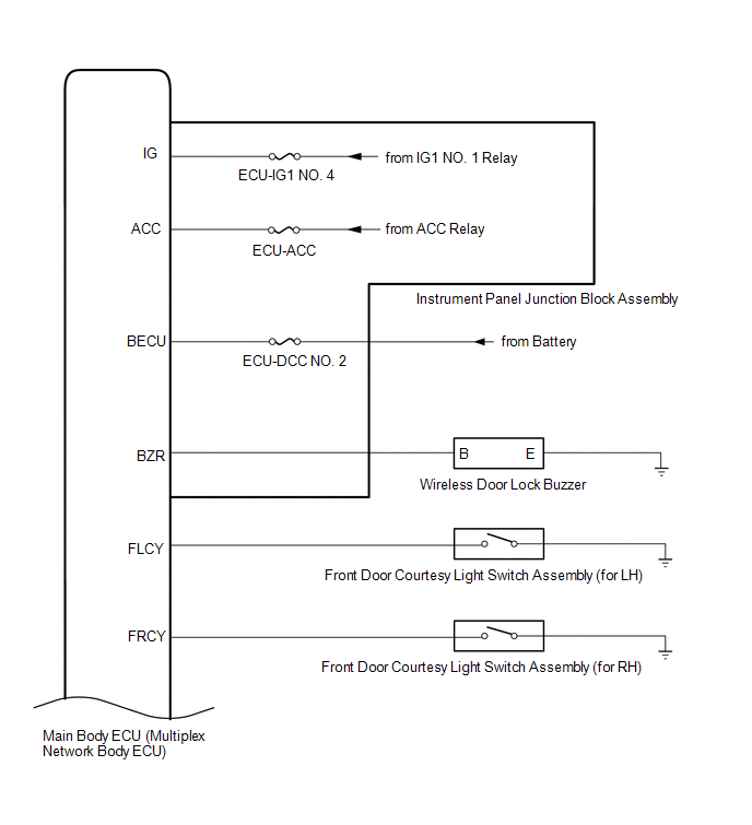
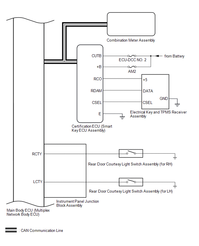
 Communication Table
|
Sender |
Receiver |
Signal |
Line |
|---|---|---|---|
|
Certification ECU (Smart Key ECU Assembly) |
Main Body ECU (Multiplex Network Body ECU) |
Wireless door lock/unlock signal |
CAN |
|
Main Body ECU (Multiplex Network Body ECU) |
Combination Meter Assembly |
Wireless door lock hazard warning light request signal |
CAN |
 System Description
SYSTEM DESCRIPTION
WIRELESS DOOR LOCK CONTROL SYSTEM
The wireless door lock control system can be used to lock and unlock all doors
from a distance. The system is controlled by an electrical key t ...
 How To Proceed With Troubleshooting
CAUTION / NOTICE / HINT
HINT:
The wireless door lock control system troubleshooting procedure is based
on the premise that the power door lock control system is operating properly.
C ...
Other materials:
Toyota CH-R Service Manual > Vacuum Pump: Removal
REMOVAL
CAUTION / NOTICE / HINT
The necessary procedures (adjustment, calibration, initialization, or registration)
that must be performed after parts are removed, installed, or replaced during vacuum
pump assembly removal/installation are shown below.
Necessary Procedure After Parts Removed/ ...
Toyota CH-R Service Manual > Seat Belt Warning System(w/ Occupant Classification System): Data List / Active Test
DATA LIST / ACTIVE TEST
DATA LIST
HINT:
Using the Techstream to read the Data List allows the values or states of switches,
sensors, actuators and other items to be read without removing any parts. This non-intrusive
inspection can be very useful because intermittent conditions or signals may ...
Toyota C-HR (AX20) 2023-2026 Owner's Manual
Toyota CH-R Owners Manual
- For safety and security
- Instrument cluster
- Operation of each component
- Driving
- Interior features
- Maintenance and care
- When trouble arises
- Vehicle specifications
- For owners
Toyota CH-R Service Manual
- Introduction
- Maintenance
- Audio / Video
- Cellular Communication
- Navigation / Multi Info Display
- Park Assist / Monitoring
- Brake (front)
- Brake (rear)
- Brake Control / Dynamic Control Systems
- Brake System (other)
- Parking Brake
- Axle And Differential
- Drive Shaft / Propeller Shaft
- K114 Cvt
- 3zr-fae Battery / Charging
- Networking
- Power Distribution
- Power Assist Systems
- Steering Column
- Steering Gear / Linkage
- Alignment / Handling Diagnosis
- Front Suspension
- Rear Suspension
- Tire / Wheel
- Tire Pressure Monitoring
- Door / Hatch
- Exterior Panels / Trim
- Horn
- Lighting (ext)
- Mirror (ext)
- Window / Glass
- Wiper / Washer
- Door Lock
- Heating / Air Conditioning
- Interior Panels / Trim
- Lighting (int)
- Meter / Gauge / Display
- Mirror (int)
- Power Outlets (int)
- Pre-collision
- Seat
- Seat Belt
- Supplemental Restraint Systems
- Theft Deterrent / Keyless Entry

0.0128