Toyota CH-R Service Manual: Installation
INSTALLATION
PROCEDURE
1. INSTALL STOP LIGHT SWITCH ASSEMBLY
|
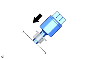
(a) Insert the stop light switch assembly until the threaded sleeve hits the pedal. NOTICE: When inserting the stop light switch assembly, support the pedal from behind so that the pedal is not pushed in. |
|
|
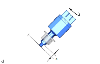
(b) Turn the stop light switch assembly 1/4 clockwise to install it. Torque: 1.5 N*m (15 kgf*cm, 13 in.*lbf) or less NOTICE: When inserting the stop light switch assembly, support the pedal from behind so that the pedal is not pushed in. |
|
(c) Connect the connector.
(d) Check the protrusion of the plunger.
Protrusion of the Plunger|
Area |
Measurement |
|---|---|
|
a |
0.6 to 2.6 mm (0.0236 to 0.102 in.) |
(e) If the protrusion is not as specified, recheck the stop light switch assembly installation and perform brake pedal adjustment if necessary.
Click here
.gif)
NOTICE:
Do not depress or support the brake pedal.
2. INSTALL NO. 1 AIR DUCT
Click here
3. INSTALL NO. 1 INSTRUMENT PANEL UNDER COVER SUB-ASSEMBLY
Click here
4. INSTALL COWL SIDE TRIM BOARD LH
Click here
5. INSTALL FRONT DOOR SCUFF PLATE LH
Click here
 Removal
REMOVAL
CAUTION / NOTICE / HINT
The necessary procedures (adjustment, calibration, initialization or registration)
that must be performed after parts are removed and installed, or replaced during ...
 Mirror (ext)
...
Other materials:
Toyota CH-R Service Manual > Quarter Garnish: Installation
INSTALLATION
CAUTION / NOTICE / HINT
HINT:
Use the same procedure for the RH side and LH side.
The following procedure is for the LH side.
PROCEDURE
1. INSTALL QUARTER PILLAR COVER SUB-ASSEMBLY
HINT:
When installing a new quarter pillar cover sub-assembly, heat the vehicle b ...
Toyota CH-R Service Manual > Front Door Speaker: Removal
REMOVAL
CAUTION / NOTICE / HINT
HINT:
Use the same procedure for the RH and LH sides.
The procedure listed below is for the LH side.
PROCEDURE
1. REMOVE FRONT DOOR INSIDE HANDLE BEZEL PLUG
Click here
2. REMOVE MULTIPLEX NETWORK MASTER SWITCH ASSEMBLY WITH FRONT ARMREST ...
Toyota C-HR (AX20) 2023-2026 Owner's Manual
Toyota CH-R Owners Manual
- For safety and security
- Instrument cluster
- Operation of each component
- Driving
- Interior features
- Maintenance and care
- When trouble arises
- Vehicle specifications
- For owners
Toyota CH-R Service Manual
- Introduction
- Maintenance
- Audio / Video
- Cellular Communication
- Navigation / Multi Info Display
- Park Assist / Monitoring
- Brake (front)
- Brake (rear)
- Brake Control / Dynamic Control Systems
- Brake System (other)
- Parking Brake
- Axle And Differential
- Drive Shaft / Propeller Shaft
- K114 Cvt
- 3zr-fae Battery / Charging
- Networking
- Power Distribution
- Power Assist Systems
- Steering Column
- Steering Gear / Linkage
- Alignment / Handling Diagnosis
- Front Suspension
- Rear Suspension
- Tire / Wheel
- Tire Pressure Monitoring
- Door / Hatch
- Exterior Panels / Trim
- Horn
- Lighting (ext)
- Mirror (ext)
- Window / Glass
- Wiper / Washer
- Door Lock
- Heating / Air Conditioning
- Interior Panels / Trim
- Lighting (int)
- Meter / Gauge / Display
- Mirror (int)
- Power Outlets (int)
- Pre-collision
- Seat
- Seat Belt
- Supplemental Restraint Systems
- Theft Deterrent / Keyless Entry

0.0105