Toyota CH-R Service Manual: Vehicle Speed Signal Circuit between Radio Receiver and Combination Meter
DESCRIPTION
- This circuit is necessary for the Automatic Sound Levelizer (ASL) built
into the radio and display receiver assembly.
The Automatic Sound Levelizer (ASL) function automatically adjusts the audio system volume level in order to compensate for increased vehicle noise (vehicle noise tends to increase as vehicle speed increases). The ASL adjusts the volume level based upon vehicle speed signals that it receives from the combination meter assembly.
- Vehicle speed signals are received from the combination meter assembly
and used to cancel "Bluetooth" function operation.
The radio and display receiver assembly recognizes that the vehicle is being driven and makes it impossible to connect or register a "Bluetooth" device while driving.
HINT:
- A voltage of 12 V or 5 V is output from each ECU and then input to the combination meter assembly. The signal is changed to a pulse signal at the transistor in the combination meter assembly. Each ECU controls the respective system based on the pulse signal.
- If a short occurs in any of the ECUs or in the wire harness connected to an ECU, all systems in the following diagram will not operate normally.
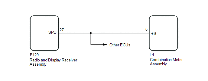
WIRING DIAGRAM
CAUTION / NOTICE / HINT
NOTICE:
- Depending on the parts that are replaced during vehicle inspection or
maintenance, performing initialization, registration or calibration may
be needed. Refer to Precaution for Navigation System.
Click here
.gif)
- When replacing the radio and display receiver assembly or navigation
ECU, always replace it with a new one. If a radio and display receiver assembly
or navigation ECU which was installed to another vehicle is used, the following
may occur:
- A communication malfunction DTC may be stored.
- The radio and display receiver assembly or navigation ECU may not operate normally.
PROCEDURE
|
1. |
CHECK VEHICLE SIGNAL (OPERATION CHECK) |
|
(a) Enter the "Vehicle Signal Check Mode" screen. Refer to Check Vehicle Signal Check Mode in Operation Check. Click here
|
|
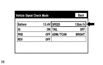
(b) While driving the vehicle, compare the "SPEED" indicator to the reading on the speedometer. Check if these readings are almost equal.
HINT:
The combination meter assembly receives the vehicle speed signal from the skid control ECU via CAN communication. Therefore, perform the following inspection referring to values on the Data List of the skid control ECU because it is the source of the vehicle speed signal.
OK:
Vehicle speed displayed on the "Vehicle Signal Check Mode" screen is almost the same as the actual vehicle speed measured using the Techstream.
Click here
| OK | .gif) |
PROCEED TO NEXT SUSPECTED AREA SHOWN IN PROBLEM SYMPTOMS TABLE |
|
.gif)
|
2. |
INSPECT COMBINATION METER ASSEMBLY (OUTPUT WAVEFORM) |
(a) Check the output waveform.
.png)
|
*a |
Component with harness connected (Combination Meter Assembly) |
- |
- |
(1) Remove the combination meter assembly with the connector still connected.
(2) Connect an oscilloscope to terminal F4-6 (+S) and body ground.
(3) Turn the engine switch on (IG).
(4) Turn a wheel slowly.
(5) Check the signal waveform according to the condition(s) in the table below.
|
Item |
Condition |
|---|---|
|
Measurement terminal |
F4-6 (+S) - Body ground |
|
Tool setting |
5 V/DIV., 20 ms./DIV. |
|
Vehicle condition |
Wheel being rotated |
OK:
The waveform is similar to that shown in the illustration.
HINT:
When the system is functioning normally, one wheel revolution generates 4 pulses. As the vehicle speed increases, the width indicated by (A) in the illustration narrows.
| NG | |
GO TO METER / GAUGE SYSTEM |
|
|
3. |
INSPECT RADIO AND DISPLAY RECEIVER ASSEMBLY (INPUT WAVEFORM) |
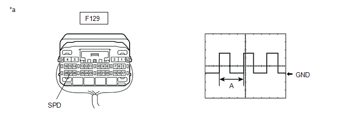
(a) Check the input waveform.
|
*a |
Component with harness connected (Radio and Display Receiver Assembly) |
- |
- |
(1) Remove the radio and display receiver assembly with the connector still connected.
(2) Connect an oscilloscope to terminal F129-27 (SPD) and body ground.
(3) Turn the engine switch on (IG).
(4) Turn a wheel slowly.
(5) Check the signal waveform according to the condition(s) in the table below.
|
Item |
Condition |
|---|---|
|
Measurement terminal |
F129-27 (SPD) - Body ground |
|
Tool setting |
5 V/DIV., 20 ms./DIV. |
|
Vehicle condition |
Wheel being rotated |
OK:
The waveform is similar to that shown in the illustration.
HINT:
When the system is functioning normally, one wheel revolution generates 4 pulses. As the vehicle speed increases, the width indicated by (A) in the illustration narrows.
| OK | |
REPLACE RADIO AND DISPLAY RECEIVER ASSEMBLY |
|
|
4. |
CHECK HARNESS AND CONNECTOR (RADIO AND DISPLAY RECEIVER ASSEMBLY - COMBINATION METER ASSEMBLY) |
(a) Disconnect the F129 radio and display receiver assembly connector.
(b) Disconnect the F4 combination meter assembly connector.
(c) Measure the resistance according to the value(s) in the table below.
Standard Resistance:
|
Tester Connection |
Condition |
Specified Condition |
|---|---|---|
|
F129-27 (SPD) - F4-6 (+S) |
Always |
Below 1 Ω |
| OK | |
PROCEED TO NEXT SUSPECTED AREA SHOWN IN PROBLEM SYMPTOMS TABLE |
| NG | |
REPAIR OR REPLACE HARNESS OR CONNECTOR |
 Black Screen
PROCEDURE
1.
CHECK DISPLAY SETTING
(a) Check that the display is not in screen off mode.
OK:
The display setting is not in screen off mode.
NG
...
 Steering Pad Switch Circuit
DESCRIPTION
This circuit sends an operation signal from the steering pad switch assembly
to the radio and display receiver assembly.
If there is an open in the circuit, the audio system cannot be ...
Other materials:
Toyota CH-R Service Manual > Power Steering System: Torque Sensor Zero Point Adjustment Undone (C1515)
DESCRIPTION
This DTC does not indicate a malfunction. The power steering ECU assembly stores
this DTC when it determines that torque sensor zero point calibration has not been
performed.
DTC No.
Detection Item
DTC Detection Condition
Trouble Area
...
Toyota CH-R Service Manual > Window Defogger System: System Description
SYSTEM DESCRIPTION
GENERAL
(a) The rear window defogger wire is attached to the inside of the rear window
and defogs the window surface quickly when the rear window defogger switch is pressed.
The indicator light on the switch illuminates while the system is operating. This
system automatica ...
Toyota C-HR (AX20) 2023-2026 Owner's Manual
Toyota CH-R Owners Manual
- For safety and security
- Instrument cluster
- Operation of each component
- Driving
- Interior features
- Maintenance and care
- When trouble arises
- Vehicle specifications
- For owners
Toyota CH-R Service Manual
- Introduction
- Maintenance
- Audio / Video
- Cellular Communication
- Navigation / Multi Info Display
- Park Assist / Monitoring
- Brake (front)
- Brake (rear)
- Brake Control / Dynamic Control Systems
- Brake System (other)
- Parking Brake
- Axle And Differential
- Drive Shaft / Propeller Shaft
- K114 Cvt
- 3zr-fae Battery / Charging
- Networking
- Power Distribution
- Power Assist Systems
- Steering Column
- Steering Gear / Linkage
- Alignment / Handling Diagnosis
- Front Suspension
- Rear Suspension
- Tire / Wheel
- Tire Pressure Monitoring
- Door / Hatch
- Exterior Panels / Trim
- Horn
- Lighting (ext)
- Mirror (ext)
- Window / Glass
- Wiper / Washer
- Door Lock
- Heating / Air Conditioning
- Interior Panels / Trim
- Lighting (int)
- Meter / Gauge / Display
- Mirror (int)
- Power Outlets (int)
- Pre-collision
- Seat
- Seat Belt
- Supplemental Restraint Systems
- Theft Deterrent / Keyless Entry

0.0105