Toyota CH-R Service Manual: Terminals Of Ecu
TERMINALS OF ECU
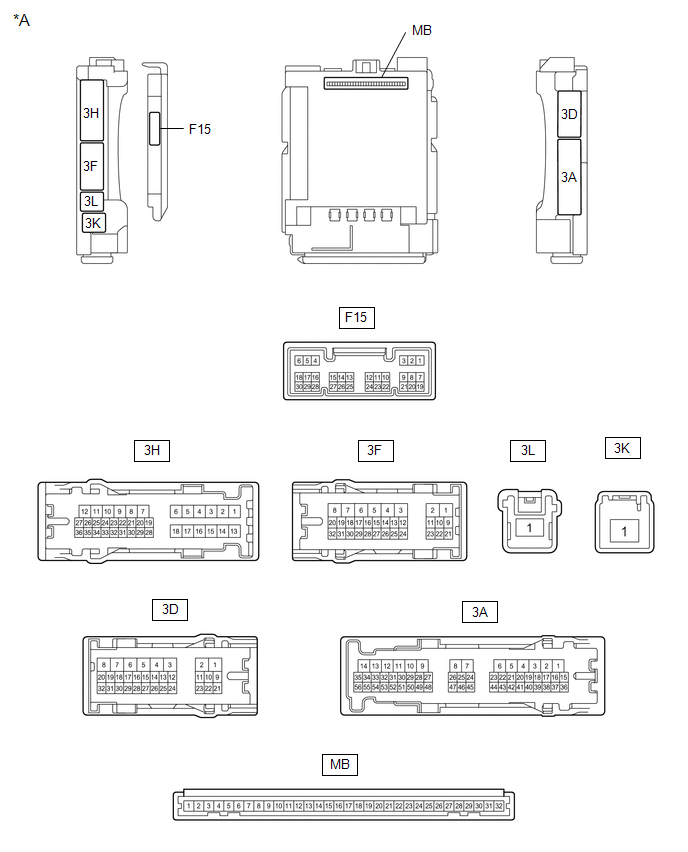
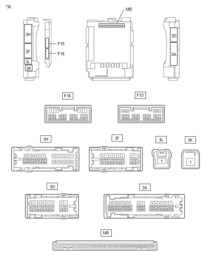
CHECK INSTRUMENT PANEL JUNCTION BLOCK ASSEMBLY AND MAIN BODY ECU (MULTIPLEX NETWORK BODY ECU)
|
*A |
1 Connector Type |
- |
- |
|
*A |
2 Connector Type |
- |
- |
(a) Disconnect the MB main body ECU (multiplex network body ECU) connector.
Click here
.gif)
(b) Measure the voltage and resistance according to the value(s) in the table below.
HINT:
Measure the values on the wire harness side with the connectors disconnected.
|
Terminal No. (Symbol) |
Wiring Color |
Terminal Description |
Condition |
Specified Condition |
|---|---|---|---|---|
|
MB-11 (GND1) - Body ground |
- |
Ground |
Always |
Below 1 Ω |
|
MB-31 (BECU) - Body ground |
- |
Battery power supply |
Always |
11 to 14 V |
|
MB-30 (ACC) - Body ground |
- |
ACC power supply |
Ignition switch ACC |
11 to 14 V |
|
Ignition switch off |
Below 1 V |
|||
|
MB-32 (IG) - Body ground |
- |
IG power supply |
Ignition switch ON |
11 to 14 V |
|
Ignition switch off |
Below 1 V |
(c) Reconnect the MB main body ECU (multiplex network body ECU) connector.
Click here
(d) Check for pulses according to the value(s) in the table below.
|
Terminal No. (Symbol) |
Wiring Color |
Terminal Description |
Condition |
Specified Condition |
|---|---|---|---|---|
|
3H-25 (LIN2) - Body ground |
LG - Body ground |
LIN communication line |
Ignition switch ON |
Pulse generation |
|
3D-17 (LIN2) - Body ground*1 |
P - Body ground |
LIN communication line |
Ignition switch ON |
Pulse generation |
- *1: w/ Double Locking System
CHECK POWER WINDOW REGULATOR MOTOR ASSEMBLY (for Driver Door)

(a) Disconnect the J2 power window regulator motor assembly (for driver door) connector.
(b) Measure the voltage and resistance according to the value(s) in the table below.
HINT:
Measure the values on the wire harness side with the connector disconnected.
|
Terminal No. (Symbol) |
Wiring Color |
Terminal Description |
Condition |
Specified Condition |
|---|---|---|---|---|
|
J2-2 (B) - Body ground |
L - Body ground |
Battery power supply |
Always |
11 to 14 V |
|
J2-1 (GND) - Body ground |
W-B - Body ground |
Ground |
Always |
Below 1 Ω |
(c) Reconnect the J2 power window regulator motor assembly (for driver door) connector.
(d) Check for pulses according to the value(s) in the table below.
|
Terminal No. (Symbol) |
Wiring Color |
Terminal Description |
Condition |
Specified Condition |
|---|---|---|---|---|
|
J2-9 (LIN) - Body ground |
R - Body ground |
LIN communication line |
Ignition switch ON |
Pulse generation |
CHECK POWER WINDOW REGULATOR MOTOR ASSEMBLY (for Front Passenger Door)

(a) Disconnect the I2 power window regulator motor assembly (for front passenger door) connector.
(b) Measure the voltage and resistance according to the value(s) in the table below.
HINT:
Measure the values on the wire harness side with the connector disconnected.
|
Terminal No. (Symbol) |
Wiring Color |
Terminal Description |
Condition |
Specified Condition |
|---|---|---|---|---|
|
I2-2 (B) - Body ground |
L - Body ground |
Battery power supply |
Always |
11 to 14 V |
|
I2-1 (GND) - Body ground |
W-B - Body ground |
Ground |
Always |
Below 1 Ω |
(c) Reconnect the I2 power window regulator motor assembly (for front passenger door) connector.
(d) Check for pulses according to the value(s) in the table below.
|
Terminal No. (Symbol) |
Wiring Color |
Terminal Description |
Condition |
Specified Condition |
|---|---|---|---|---|
|
I2-9 (LIN) - Body ground |
P - Body ground |
LIN communication line |
Ignition switch ON |
Pulse generation |
CHECK POWER WINDOW REGULATOR MOTOR ASSEMBLY (for Rear RH Door)

(a) Disconnect the K2 power window regulator motor assembly (for rear RH door) connector.
(b) Measure the voltage and resistance according to the value(s) in the table below.
HINT:
Measure the values on the wire harness side with the connector disconnected.
|
Terminal No. (Symbol) |
Wiring Color |
Terminal Description |
Condition |
Specified Condition |
|---|---|---|---|---|
|
K2-2 (B) - Body ground |
R - Body ground |
Battery power supply |
Always |
11 to 14 V |
|
K2-1 (GND) - Body ground |
W-B - Body ground |
Ground |
Always |
Below 1 Ω |
(c) Reconnect the K2 power window regulator motor assembly (for rear RH door) connector.
(d) Check for pulses according to the value(s) in the table below.
|
Terminal No. (Symbol) |
Wiring Color |
Terminal Description |
Condition |
Specified Condition |
|---|---|---|---|---|
|
K2-9 (LIN) - Body ground |
LG - Body ground |
LIN communication line |
Ignition switch ON |
Pulse generation |
CHECK POWER WINDOW REGULATOR MOTOR ASSEMBLY (for Rear LH Door)

(a) Disconnect the L2 power window regulator motor assembly (for rear LH door) connector.
(b) Measure the voltage and resistance according to the value(s) in the table below.
HINT:
Measure the values on the wire harness side with the connector disconnected.
|
Terminal No. (Symbol) |
Wiring Color |
Terminal Description |
Condition |
Specified Condition |
|---|---|---|---|---|
|
L2-2 (B) - Body ground |
R - Body ground |
Battery power supply |
Always |
11 to 14 V |
|
L2-1 (GND) - Body ground |
W-B - Body ground |
Ground |
Always |
Below 1 Ω |
(c) Reconnect the L2 power window regulator motor assembly (for rear LH door) connector.
(d) Check for pulses according to the value(s) in the table below.
|
Terminal No. (Symbol) |
Wiring Color |
Terminal Description |
Condition |
Specified Condition |
|---|---|---|---|---|
|
L2-9 (LIN) - Body ground |
LG - Body ground |
LIN communication line |
Ignition switch ON |
Pulse generation |
CHECK MULTIPLEX NETWORK MASTER SWITCH ASSEMBLY

(a) Disconnect the J6 multiplex network master switch assembly connector.
(b) Measure the voltage and resistance according to the value(s) in the table below.
HINT:
Measure the values on the wire harness side with the connector disconnected.
|
Terminal No. (Symbol) |
Wiring Color |
Terminal Description |
Condition |
Specified Condition |
|---|---|---|---|---|
|
J6-11 (B) - Body ground |
B - Body ground |
Battery power supply |
Always |
11 to 14 V |
|
J6-12 (GND) - Body ground |
W-B - Body ground |
Ground |
Always |
Below 1 Ω |
(c) Reconnect the J6 multiplex network master switch assembly connector.
(d) Check for pulses according to the value(s) in the table below.
|
Terminal No. (Symbol) |
Wiring Color |
Terminal Description |
Condition |
Specified Condition |
|---|---|---|---|---|
|
J6-17 (LIN1) - Body ground |
P - Body ground |
LIN communication line |
Ignition switch ON |
Pulse generation |
|
J6-16 (LIN2) - Body ground |
R - Body ground |
LIN communication line |
Ignition switch ON |
Pulse generation |
CHECK CERTIFICATION ECU (SMART KEY ECU ASSEMBLY) (w/ Smart Key System)
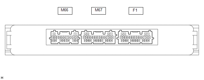
(a) Disconnect the F1 certification ECU (smart key ECU assembly) connector.
(b) Measure the voltage and resistance according to the value(s) in the table below.
HINT:
Measure the values on the wire harness side with the connector disconnected.
|
Terminal No. (Symbol) |
Wiring Color |
Terminal Description |
Condition |
Specified Condition |
|---|---|---|---|---|
|
F1-18 (E) - Body ground |
W-B - Body ground |
Ground |
Always |
Below 1 Ω |
|
F1-4 (+B) - Body ground |
L - Body ground |
+B power supply |
Always |
11 to 14 V |
(c) Reconnect the F1 certification ECU (smart key ECU assembly) connector.
(d) Check for pulses according to the value(s) in the table below.
|
Terminal No. (Symbol) |
Wiring Color |
Terminal Description |
Condition |
Specified Condition |
|---|---|---|---|---|
|
F1-13 (LIN) - Body ground |
B - Body ground |
LIN communication line |
Ignition switch ON |
Pulse generation |
CHECK STEERING LOCK ECU (STEERING LOCK ACTUATOR OR UPPER BRACKET ASSEMBLY) (w/ Smart Key System)

(a) Disconnect the F78 steering lock ECU (steering lock actuator or upper bracket assembly) connector.
(b) Measure the resistance and voltage according to the value(s) in the table below.
|
Terminal No. (Symbol) |
Wiring Color |
Terminal Description |
Condition |
Specified Condition |
|---|---|---|---|---|
|
F78-1 (GND) - Body ground |
W-B Body ground |
Ground |
Always |
Below 1 Ω |
|
F78-7 (B) - Body ground |
L - Body ground |
Battery power supply |
Always |
11 to 14 V |
(c) Reconnect the F78 steering lock ECU (steering lock actuator or upper bracket assembly) connector.
(d) Check for pulses according to the value(s) in the table below.
|
Terminal No. (Symbol) |
Wiring Color |
Terminal Description |
Condition |
Specified Condition |
|---|---|---|---|---|
|
F78-5 (LIN) - Body ground |
V - Body ground |
LIN communication line |
Ignition switch ON |
Pulse generation |
CHECK ID CODE BOX (IMMOBILISER CODE ECU) (w/ Smart Key System)

(a) Disconnect the F21 ID code box (immobiliser code ECU) connector.
(b) Measure the voltage and resistance according to the value(s) in the table below.
HINT:
Measure the values on the wire harness side with the connector disconnected.
|
Terminal No. (Symbol) |
Wiring Color |
Terminal Description |
Condition |
Specified Condition |
|---|---|---|---|---|
|
F21-5 (GND) - Body ground |
W-B - Body ground |
Ground |
Always |
Below 1 Ω |
|
F21-1 (+B) - Body ground |
W - Body ground |
+B power supply |
Always |
11 to 14 V |
(c) Reconnect the F21 ID code box (immobiliser code ECU) connector.
(d) Check for pulses according to the value(s) in the table below.
|
Terminal No. (Symbol) |
Wiring Color |
Terminal Description |
Condition |
Specified Condition |
|---|---|---|---|---|
|
F21-2 (LIN1) - Body ground |
B - Body ground |
LIN communication line |
Ignition switch ON |
Pulse generation |
CHECK DOUBLE LOCK DOOR CONTROL RELAY ASSEMBLY (w/ Double Locking System)

(a) Disconnect the F14 double lock door control relay assembly connector.
(b) Measure the voltage and resistance according to the value(s) in the table below.
HINT:
Measure the values on the wire harness side with the connector disconnected.
|
Terminal No. (Symbol) |
Wiring Color |
Terminal Description |
Condition |
Specified Condition |
|---|---|---|---|---|
|
F14-12 (+B) - Body ground |
BE - Body ground |
Battery power supply |
Always |
11 to 14 V |
|
F14-11 (CPUB) - Body ground |
SB - Body ground |
Battery power supply |
Always |
11 to 14 V |
|
F14-7 (GND) - Body ground |
LA - Body ground |
Ground |
Always |
Below 1 Ω |
(c) Reconnect the F14 double lock door control relay assembly connector.
(d) Check for pulses according to the value(s) in the table below.
|
Terminal No. (Symbol) |
Wiring Color |
Terminal Description |
Condition |
Specified Condition |
|---|---|---|---|---|
|
F14-9 (LIN) - Body ground |
P - Body ground |
LIN communication line |
Double lock unset |
Pulse generation |
 How To Proceed With Troubleshooting
CAUTION / NOTICE / HINT
HINT:
Use the following procedure to troubleshoot the LIN communication system.
*: Use the Techstream.
PROCEDURE
1.
VEHICLE BROU ...
 Diagnosis System
DIAGNOSIS SYSTEM
DESCRIPTION
The main body ECU (multiplex network body ECU) and certification ECU (smart key
ECU assembly) control the LIN communication system. LIN communication system data
and ...
Other materials:
Toyota CH-R Owners Manual > Dynamic radar cruise control with full-speed range: Adjusting the set speed
To change the set speed, operate the lever until the desired set speed is displayed.
Increases the speed
(Except when the vehicle has been stopped by system control in vehicle- to-vehicle
distance control mode)
Decreases the speed
Fine adjustment: Momentarily move the lever in the ...
Toyota CH-R Service Manual > Front Wheel Alignment: Adjustment
ADJUSTMENT
CAUTION / NOTICE / HINT
The necessary procedures (adjustment, calibration, initialization, or registration)
that must be performed after completing the front wheel alignment procedure are
shown below.
Necessary Procedures After Procedure Performed
Replaced Part or Perfo ...
Toyota C-HR (AX20) 2023-2026 Owner's Manual
Toyota CH-R Owners Manual
- For safety and security
- Instrument cluster
- Operation of each component
- Driving
- Interior features
- Maintenance and care
- When trouble arises
- Vehicle specifications
- For owners
Toyota CH-R Service Manual
- Introduction
- Maintenance
- Audio / Video
- Cellular Communication
- Navigation / Multi Info Display
- Park Assist / Monitoring
- Brake (front)
- Brake (rear)
- Brake Control / Dynamic Control Systems
- Brake System (other)
- Parking Brake
- Axle And Differential
- Drive Shaft / Propeller Shaft
- K114 Cvt
- 3zr-fae Battery / Charging
- Networking
- Power Distribution
- Power Assist Systems
- Steering Column
- Steering Gear / Linkage
- Alignment / Handling Diagnosis
- Front Suspension
- Rear Suspension
- Tire / Wheel
- Tire Pressure Monitoring
- Door / Hatch
- Exterior Panels / Trim
- Horn
- Lighting (ext)
- Mirror (ext)
- Window / Glass
- Wiper / Washer
- Door Lock
- Heating / Air Conditioning
- Interior Panels / Trim
- Lighting (int)
- Meter / Gauge / Display
- Mirror (int)
- Power Outlets (int)
- Pre-collision
- Seat
- Seat Belt
- Supplemental Restraint Systems
- Theft Deterrent / Keyless Entry

0.008