Toyota CH-R Service Manual: On-vehicle Inspection
ON-VEHICLE INSPECTION
CAUTION / NOTICE / HINT
NOTICE:
If the battery is weak or if the engine is difficult to start, recharge the battery and perform inspections again before returning the vehicle to the customer.
PROCEDURE
1. CHECK BATTERY CONDITION
(a) Check the battery for damage or deformation. If severe damage, deformation or leakage is found, replace the battery.
(b) Check the electrolyte level in each cell.
(1) For maintenance-free batteries:
- If the electrolyte level is below the lower line, replace the battery.
- If the electrolyte level is above the lower line, check the battery
voltage when cranking the engine. If the voltage is less than 9.6 V, recharge
or replace the battery.
HINT:
Before checking the battery voltage, turn off all the electrical systems (headlights, blower motor, rear defogger, etc.).
(2) For non-maintenance-free batteries:
- If the electrolyte level is below the lower line, add distilled water
to each cell. Then, recharge the battery and check the electrolyte specific
gravity.
Standard Specific Gravity:
1.25 or higher at 20°C (68°F)
- If the electrolyte level is above the lower line, check the battery
voltage when cranking the engine. If the battery voltage is less than 9.6
V, recharge or replace the battery.
HINT:
Before checking the battery voltage, turn off all the electrical systems (headlights, blower motor, rear defogger, etc.).
(c) Check the voltage.
(1) Turn the ignition switch off and turn on the headlights for 20 to 30 seconds. This will remove the surface charge from the battery.
(2) Measure the battery voltage according to the value(s) in the table below.
Standard Voltage:
|
Tester Connection |
Condition |
Specified Condition |
|---|---|---|
|
Positive (+) terminal - Negative (-) terminal |
20°C (68°F) |
12.3 V or higher |
If the result is not as specified, recharge or replace the battery.
2. CHECK BATTERY TERMINAL
(a) Check that the battery terminals are not loose or corroded.
If a terminal is loose or corroded, tighten or clean the terminal.
Torque:
Positive (+) Battery Terminal :
5.4 N·m {55 kgf·cm, 48 in·lbf}
Negative (-) Battery Terminal :
5.4 N·m {55 kgf·cm, 48 in·lbf}
3. CHECK FUSES
(a) Measure the resistance of each fuse for the charging system.
HINT:
The fuses shown in System Diagram are related to the charging system.
Standard Resistance:
Below 1 Ω
- If the result is not as specified, replace the fuse.
4. INSPECT FAN AND GENERATOR V BELT
Click here
.gif)
5. INSPECT GENERATOR WITH REGULATOR ASSEMBLY WIRING
(a) Visually check the generator assembly wiring.
(1) Check that the wiring is in good condition.
6. CHECK FOR ABNORMAL NOISE
(a) Listen for abnormal noises from the generator assembly.
(1) Check that no abnormal noises are heard from the generator assembly while the engine is running.
If noise occurs, check the generator assembly.
Click here
7. INSPECT CHARGE WARNING LIGHT
(a) Turn the ignition switch to ON.
(b) Check that the charge warning light comes on.
(c) Start the engine and check that the charge warning light goes off.
If the charge warning light does not operate as specified, troubleshoot the charge warning light.
Click here
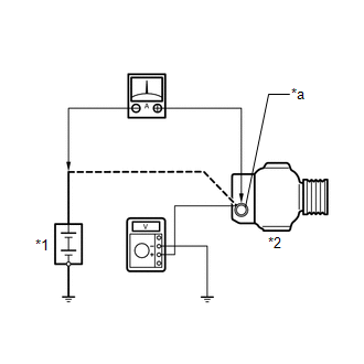
8. INSPECT CHARGING CIRCUIT WITHOUT LOAD
|
(a) Connect a voltmeter and an ammeter to the charging circuit as follows. HINT: If a battery/generator assembly tester is available, connect the tester to the charging circuit in accordance with the manufacturer's instructions. (1) Disconnect the wire from terminal B of the generator assembly, and then connect it to the negative (-) lead of the ammeter. (2) Connect the ammeter positive (+) lead to terminal B of the generator assembly. (3) Connect the voltmeter positive (+) lead to the terminal B of the generator assembly. (4) Ground the voltmeter negative (-) lead. |
|
(b) Check the charging circuit.
(1) Maintain the engine speed at 2000 rpm and check the readings on the ammeter and voltmeter.
Standard Current:
10 A or more
Standard Voltage:
13.2 to 14.8 V
If the result is not as specified, repair or replace the generator assembly.
HINT:
If the result is not fully charged, the ammeter reading will sometimes be more than the standard current.
9. INSPECT CHARGING CIRCUIT WITH LOAD
(a) With the engine running at 2000 rpm, turn the high beam headlights on and turn the heater blower switch to the "HI" position.
(b) Check the reading on the ammeter.
Standard Current:
30 A or more
If the result is not as specified, repair or replace the generator assembly.
HINT:
If the battery is fully charged, the reading will sometimes be less than the standard. If this is the case, add more electrical load (operate the wipers, rear window defogger, etc.) and check the reading on the ammeter again.
 Diagnostic Trouble Code Chart
DIAGNOSTIC TROUBLE CODE CHART
Charging System
DTC No.
Detection Item
Link
P161A
Lost Communication with Alternator
...
 Lost Communication with Alternator (P161A)
DESCRIPTION
The ECM and generator assembly detect reception errors respectively.
The generator assembly reception error detected by the generator assembly is
sent to the ECM via LIN communication. ...
Other materials:
Toyota CH-R Owners Manual > Adjusting the steering wheel and mirrors: Outside rear view mirrors
Adjustment procedure
1. To select a mirror to adjust, turn the switch.
Left
Right
2. To adjust the mirror, operate the switch.
Up
Right
Down
Left
Folding and extending the mirrors
Manual type
Push the mirror back in the direction of the rear of the vehicle.
Powe ...
Toyota CH-R Service Manual > Occupant Classification System: Precaution
PRECAUTION
GENERAL PRECAUTION
(a) The following conditions may be interpreted as a malfunction even though
they are normal operation:
An object is placed on the passenger seat and the system judges that
an adult is seated. As the occupant classification system detects and classifies ...
Toyota C-HR (AX20) 2023-2026 Owner's Manual
Toyota CH-R Owners Manual
- For safety and security
- Instrument cluster
- Operation of each component
- Driving
- Interior features
- Maintenance and care
- When trouble arises
- Vehicle specifications
- For owners
Toyota CH-R Service Manual
- Introduction
- Maintenance
- Audio / Video
- Cellular Communication
- Navigation / Multi Info Display
- Park Assist / Monitoring
- Brake (front)
- Brake (rear)
- Brake Control / Dynamic Control Systems
- Brake System (other)
- Parking Brake
- Axle And Differential
- Drive Shaft / Propeller Shaft
- K114 Cvt
- 3zr-fae Battery / Charging
- Networking
- Power Distribution
- Power Assist Systems
- Steering Column
- Steering Gear / Linkage
- Alignment / Handling Diagnosis
- Front Suspension
- Rear Suspension
- Tire / Wheel
- Tire Pressure Monitoring
- Door / Hatch
- Exterior Panels / Trim
- Horn
- Lighting (ext)
- Mirror (ext)
- Window / Glass
- Wiper / Washer
- Door Lock
- Heating / Air Conditioning
- Interior Panels / Trim
- Lighting (int)
- Meter / Gauge / Display
- Mirror (int)
- Power Outlets (int)
- Pre-collision
- Seat
- Seat Belt
- Supplemental Restraint Systems
- Theft Deterrent / Keyless Entry

0.0102