Toyota CH-R Service Manual: Lost Communication with Alternator (P161A)
DESCRIPTION
The ECM and generator assembly detect reception errors respectively.
The generator assembly reception error detected by the generator assembly is sent to the ECM via LIN communication. If an error occurs in the ECM or generator assembly, the ECM determines there is a LIN communication error and stores this DTC.
|
DTC No. |
Detection Item |
DTC Detection Condition |
Trouble Area |
|---|---|---|---|
|
P161A |
Lost Communication with Alternator |
Generator assembly or ECM communication stop for about 17 minutes or more with the ignition switch ON. (1 trip detection logic) |
|
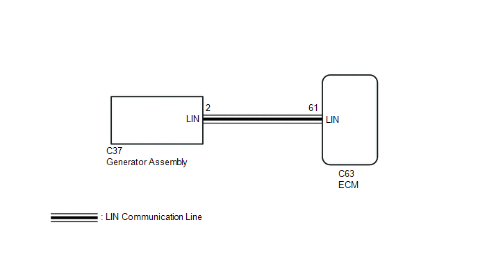
WIRING DIAGRAM
PROCEDURE
|
1. |
CHECK CHARGING SYSTEM |
(a) Check the charging system.
Click here
.gif)
| NG | .gif) |
REPAIR OR REPLACE CHARGING SYSTEM |
|
.gif)
|
2. |
CHECK HARNESS AND CONNECTOR (ECM - GENERATOR WITH REGULATOR ASSEMBLY) |
(a) Disconnect the C63 ECM connector.
(b) Disconnect the C37 generator assembly connector.
(c) Measure the resistance according to the value(s) in the table below.
Standard Resistance:
|
Tester Connection |
Condition |
Specified Condition |
|---|---|---|
|
C63-61 (LIN) - C37-2 (LIN) |
Always |
Below 1 Ω |
|
C63-61 (LIN), C37-2 (LIN) - body ground |
Always |
10 kΩ or higher |
| OK | |
REPLACE GENERATOR ASSEMBLY |
| NG | |
REPAIR OR REPLACE HARNESS OR CONNECTOR |
 On-vehicle Inspection
ON-VEHICLE INSPECTION
CAUTION / NOTICE / HINT
NOTICE:
If the battery is weak or if the engine is difficult to start, recharge the battery
and perform inspections again before returning the vehicl ...
 Charging Failure
PROCEDURE
1.
CHECK GENERATOR PULLEY WITH CLUTCH (ON-VEHICLE INSPECTION)
(a) Start the engine and visually check that the generator rotor assembly (fan)
in the gener ...
Other materials:
Toyota CH-R Service Manual > Steering Heater Switch: Installation
INSTALLATION
PROCEDURE
1. INSTALL STEERING HEATER SWITCH
(a) Engage the 2 claws to install the steering heater switch to the fuse box
opening cover.
Install in this direction
2. INSTALL FUSE BOX OPENING COVER
Click here
3. CONNECT HOOD LOCK CONTROL LEV ...
Toyota CH-R Service Manual > Front Wiper Motor: Components
COMPONENTS
ILLUSTRATION
*1
WINDSHIELD OUTSIDE MOULDING LH
*2
WINDSHIELD OUTSIDE MOULDING RH
ILLUSTRATION
*A
for USA and Canada
*B
except USA and Canada
*1
COWL TOP VEN ...
Toyota C-HR (AX20) 2023-2026 Owner's Manual
Toyota CH-R Owners Manual
- For safety and security
- Instrument cluster
- Operation of each component
- Driving
- Interior features
- Maintenance and care
- When trouble arises
- Vehicle specifications
- For owners
Toyota CH-R Service Manual
- Introduction
- Maintenance
- Audio / Video
- Cellular Communication
- Navigation / Multi Info Display
- Park Assist / Monitoring
- Brake (front)
- Brake (rear)
- Brake Control / Dynamic Control Systems
- Brake System (other)
- Parking Brake
- Axle And Differential
- Drive Shaft / Propeller Shaft
- K114 Cvt
- 3zr-fae Battery / Charging
- Networking
- Power Distribution
- Power Assist Systems
- Steering Column
- Steering Gear / Linkage
- Alignment / Handling Diagnosis
- Front Suspension
- Rear Suspension
- Tire / Wheel
- Tire Pressure Monitoring
- Door / Hatch
- Exterior Panels / Trim
- Horn
- Lighting (ext)
- Mirror (ext)
- Window / Glass
- Wiper / Washer
- Door Lock
- Heating / Air Conditioning
- Interior Panels / Trim
- Lighting (int)
- Meter / Gauge / Display
- Mirror (int)
- Power Outlets (int)
- Pre-collision
- Seat
- Seat Belt
- Supplemental Restraint Systems
- Theft Deterrent / Keyless Entry

0.0094