
Toyota CH-R Service Manual: Charging Failure
PROCEDURE
|
1. |
CHECK GENERATOR PULLEY WITH CLUTCH (ON-VEHICLE INSPECTION) |
(a) Start the engine and visually check that the generator rotor assembly (fan) in the generator assembly is operating.
OK:
The generator rotor assembly (fan) is operating.
| NG | .gif) |
REPLACE GENERATOR PULLEY WITH CLUTCH |
|
.gif)
|
2. |
CHECK GENERATOR PULLEY WITH CLUTCH (UNIT INSPECTION) |
(a) Remove the generator assembly.
Click here
.gif)
(b) Check the installation condition of the generator pulley cap.
OK:
The generator pulley cap is not loose or missing.
(c) Check for forming of particles due to friction (for dry type pulley) or grease leaks (for wet type pulley).
OK:
There are no large amounts of particles (for dry type pulley) or grease leaks (for wet type pulley).
(d) Check the generator pulley with clutch for misalignment (interference with the generator assembly).
OK:
The generator pulley with clutch is not misaligned (no interference with the generator assembly).
|
(e) Turn the generator pulley with clutch clockwise and counterclockwise by hand and check for noise. OK: Noise does not occur when turned in either direction. |
|
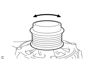
(f) Turn the generator pulley with clutch clockwise and counterclockwise by hand and visually check for runout.
OK:
The generator pulley with clutch does not have runout.
|
(g) Hold the generator rotor assembly (fan) in the generator assembly with a screwdriver with its tip wrapped with protective tape, and check that the generator pulley with clutch locks when turned clockwise and turns freely when turned counterclockwise. OK: The generator pulley with clutch locks when turned clockwise and turns freely when turned counterclockwise. |
|
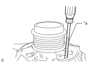
| OK | |
REPAIR OR REPLACE GENERATOR ASSEMBLY |
| NG | |
REPLACE GENERATOR PULLEY WITH CLUTCH |
 Lost Communication with Alternator (P161A)
DESCRIPTION
The ECM and generator assembly detect reception errors respectively.
The generator assembly reception error detected by the generator assembly is
sent to the ECM via LIN communication. ...
 Noise Occurs from V-ribbed Belt or Generator Assembly
PROCEDURE
1.
CONFIRM PROBLEM SYMPTOM
(a) Confirm the problem symptom.
Symptom
Proceed to
Noise occurs from V-ribbed belt.
...
Other materials:
Toyota CH-R Service Manual > Immobiliser System(w/o Smart Key System): Theft Deterrent System Communication Line High Fixation (B279A)
DESCRIPTION
If the communication line (EFIO-IMI) to the transponder key ECU assembly is stuck
high (e.g. shorted to +B), the ECM stores this DTC.
DTC No.
Detection Item
DTC Detection Condition
Trouble Area
Note
B279A
...
Toyota CH-R Service Manual > Safety Connect System: Manual (SOS) Switch Red Indicator Malfunction (B1570)
DESCRIPTION
This DTC is stored when the DCM (Telematics Transceiver) detects an open or short
in the manual (SOS) switch red indicator circuit of the manual (SOS) switch.
The manual (SOS) switch red indicator illuminates for 2 seconds and goes off
when the ignition switch turned to ON. If a ma ...
Toyota C-HR (AX20) 2023-2026 Owner's Manual
Toyota CH-R Owners Manual
- For safety and security
- Instrument cluster
- Operation of each component
- Driving
- Interior features
- Maintenance and care
- When trouble arises
- Vehicle specifications
- For owners
Toyota CH-R Service Manual
- Introduction
- Maintenance
- Audio / Video
- Cellular Communication
- Navigation / Multi Info Display
- Park Assist / Monitoring
- Brake (front)
- Brake (rear)
- Brake Control / Dynamic Control Systems
- Brake System (other)
- Parking Brake
- Axle And Differential
- Drive Shaft / Propeller Shaft
- K114 Cvt
- 3zr-fae Battery / Charging
- Networking
- Power Distribution
- Power Assist Systems
- Steering Column
- Steering Gear / Linkage
- Alignment / Handling Diagnosis
- Front Suspension
- Rear Suspension
- Tire / Wheel
- Tire Pressure Monitoring
- Door / Hatch
- Exterior Panels / Trim
- Horn
- Lighting (ext)
- Mirror (ext)
- Window / Glass
- Wiper / Washer
- Door Lock
- Heating / Air Conditioning
- Interior Panels / Trim
- Lighting (int)
- Meter / Gauge / Display
- Mirror (int)
- Power Outlets (int)
- Pre-collision
- Seat
- Seat Belt
- Supplemental Restraint Systems
- Theft Deterrent / Keyless Entry

0.0093