Toyota CH-R Service Manual: Inspection
INSPECTION
PROCEDURE
1. INSPECT SHIFT LOCK CONTROL UNIT ASSEMBLY (w/o Smart Key System)
HINT:
If the results of the following inspections are as specified but a malfunction has occurred, replace the shift lock control unit assembly.
(a) Inspect the wire harness.
|
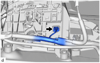
(1) Disconnect the shift lock control ECU connector. |
|
|
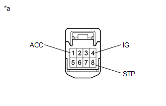
(2) Measure the voltage according to the value(s) in the table below. Standard Voltage:
If the result is not as specified, repair or replace the wire harness or connector. |
|
|
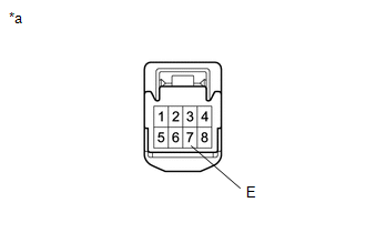
(3) Measure the resistance according to the value(s) in the table below. Standard Resistance:
If the result is not as specified, repair or replace the wire harness or connector. |
|
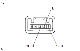
(b) Inspect the key interlock solenoid operation signal.
|
(1) Connect the shift lock control ECU connector. |
|
|
(2) Measure the voltage according to the value(s) in the table below. Standard Voltage:
If the result is not as specified, replace the shift lock control unit assembly. HINT: Do not disconnect the shift lock control ECU connector. |
|
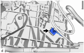
(c) Inspect the shift lock solenoid.
|
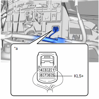
(1) Disconnect the shift lock solenoid connector. |
|
|
(2) Measure the resistance according to the value(s) in the table below. Standard Resistance:
If the result is not as specified, replace the shift lock control unit assembly. |
|
2. INSPECT SHIFT LOCK CONTROL UNIT ASSEMBLY (w/ Smart Key System)
HINT:
If the results of the following inspections are as specified but a malfunction has occurred, replace the shift lock control unit assembly.
(a) Inspect the wire harness.
|
(1) Disconnect the shift lock control ECU connector. |
|
|
(2) Measure the voltage according to the value(s) in the table below. Standard Voltage:
If the result is not as specified, repair or replace the wire harness or connector. |
|
|
(3) Measure the resistance according to the value(s) in the table below. Standard Resistance:
If the result is not as specified, repair or replace the wire harness or connector. |
|
(b) Inspect the shift lock solenoid.
|
(1) Disconnect the shift lock solenoid connector. |
|
|
(2) Measure the resistance according to the value(s) in the table below. Standard Resistance:
If the result is not as specified, replace the shift lock control unit assembly. |
|
3. INSPECT TRANSMISSION CONTROL SWITCH (SHIFT LOCK CONTROL UNIT ASSEMBLY)
|
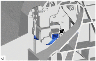
(a) Disconnect the connector from the shift lock control unit assembly. |
|
|
(b) Measure the resistance according to the value(s) in the table below. Standard Resistance:
If the result is not as specified, replace the shift lock control unit assembly. |
|
 Disassembly
DISASSEMBLY
PROCEDURE
1. REMOVE SHIFTING HOLE COVER SUB-ASSEMBLY
(a) Disengage the 4 guides and 6 claws to remove the shifting hole cover
sub-assembly from the upper console panel su ...
 Reassembly
REASSEMBLY
PROCEDURE
1. INSTALL SHIFT LEVER HOUSING BRACKET SUB-ASSEMBLY
(a) Engage the 4 claws to install the shift lever housing bracket sub-assembly
to the shift lock control unit ...
Other materials:
Toyota CH-R Service Manual > Audio And Visual System(for Radio Receiver Type): Parts Location
PARTS LOCATION
ILLUSTRATION
*1
MAP LIGHT ASSEMBLY (TELEPHONE MICROPHONE ASSEMBLY)
-
-
ILLUSTRATION
*1
FRONT NO. 1 SPEAKER ASSEMBLY LH
*2
FRONT NO. 1 SPEAKER ASSEMBLY RH
*3
...
Toyota CH-R Service Manual > Front Evaporator Temperature Sensor(for Valeo Made): Components
COMPONENTS
ILLUSTRATION
*1
AIR CONDITIONING AMPLIFIER ASSEMBLY
*2
AIR CONDITIONING HARNESS ASSEMBLY
*3
HEATER RADIATOR UNIT SUB-ASSEMBLY
-
-
ILLUSTRATION
*A
w/o PTC He ...
Toyota C-HR (AX20) 2023-2026 Owner's Manual
Toyota CH-R Owners Manual
- For safety and security
- Instrument cluster
- Operation of each component
- Driving
- Interior features
- Maintenance and care
- When trouble arises
- Vehicle specifications
- For owners
Toyota CH-R Service Manual
- Introduction
- Maintenance
- Audio / Video
- Cellular Communication
- Navigation / Multi Info Display
- Park Assist / Monitoring
- Brake (front)
- Brake (rear)
- Brake Control / Dynamic Control Systems
- Brake System (other)
- Parking Brake
- Axle And Differential
- Drive Shaft / Propeller Shaft
- K114 Cvt
- 3zr-fae Battery / Charging
- Networking
- Power Distribution
- Power Assist Systems
- Steering Column
- Steering Gear / Linkage
- Alignment / Handling Diagnosis
- Front Suspension
- Rear Suspension
- Tire / Wheel
- Tire Pressure Monitoring
- Door / Hatch
- Exterior Panels / Trim
- Horn
- Lighting (ext)
- Mirror (ext)
- Window / Glass
- Wiper / Washer
- Door Lock
- Heating / Air Conditioning
- Interior Panels / Trim
- Lighting (int)
- Meter / Gauge / Display
- Mirror (int)
- Power Outlets (int)
- Pre-collision
- Seat
- Seat Belt
- Supplemental Restraint Systems
- Theft Deterrent / Keyless Entry

0.015