Toyota CH-R Service Manual: Disassembly
DISASSEMBLY
PROCEDURE
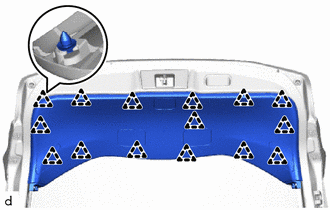
1. REMOVE PACKAGE TRAY TRIM PANEL ASSEMBLY (w/ Package Tray Trim)
Click here
.gif)
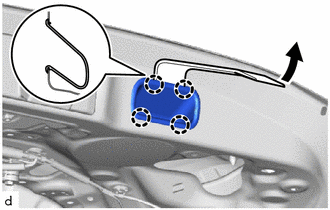
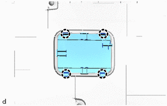
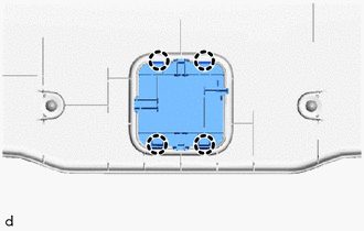
2. REMOVE TONNEAU COVER ASSEMBLY (w/ Tonneau Cover)
Click here
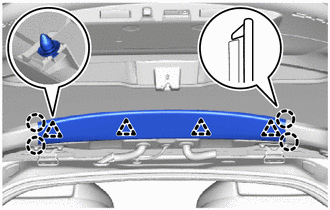
3. REMOVE BACK DOOR TRIM UPPER PANEL ASSEMBLY
|
(a) Disengage the claws and clips to remove the back door trim upper panel assembly. |
|
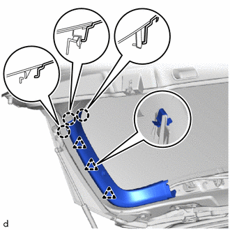
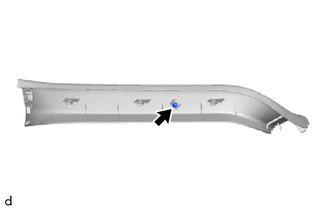
4. REMOVE BACK DOOR SIDE GARNISH LH
|
(a) Disengage the claws and clips to remove the back door side garnish LH. |
|
5. REMOVE BACK DOOR SIDE GARNISH RH
HINT:
Use the same procedure as for the LH side.
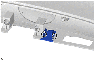
6. REMOVE PACKAGE TRAY TRIM GARNISH HOOK
HINT:
Use the same procedure for the RH side and LH side.
|
(a) Remove the screw. |
|
|
(b) Remove the package tray trim garnish hook. |
|
7. REMOVE BACK DOOR TRIM PANEL ASSEMBLY
|
(a) Disengage the clips to remove the back door trim panel assembly. |
|
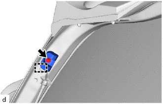
8. REMOVE DOOR PULL HANDLE
|
(a) Using a moulding remover D, disengage the claws to remove the door pull handle. |
|
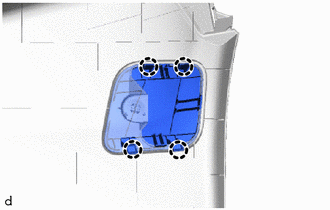
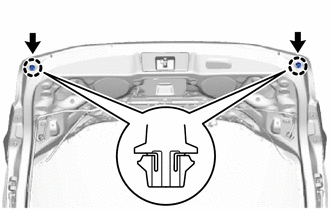
9. REMOVE NO. 1 BACK DOOR SERVICE HOLE COVER
|
(a) Disengage the claws to remove the No. 1 back door service hole cover. |
|
10. REMOVE NO. 2 BACK DOOR SERVICE HOLE COVER
HINT:
Use the same procedure as for the No. 1 back door service hole cover.
11. REMOVE NO. 3 BACK DOOR SERVICE HOLE COVER
|
(a) Disengage the claws to remove the No. 3 back door service hole cover. |
|
12. REMOVE BACK DOOR SERVICE HOLE COVER LH
|
(a) Disengage the claws to remove the back door service hole cover LH. |
|
13. REMOVE BACK DOOR SERVICE HOLE COVER RH
HINT:
Use the same procedure as for the LH side.
14. REMOVE BACK DOOR LOCK COVER
(a) Disengage the claws.
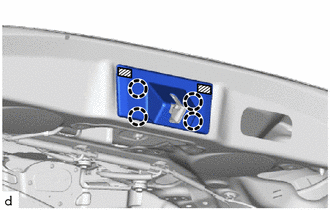
.png) |
Double-sided Tape |
(b) Remove the double-sided tape and back door lock cover.
NOTICE:
Remove any remaining double-sided tape from the back door.
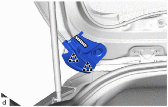
15. REMOVE BACK DOOR LOCK ASSEMBLY
Click here
16. REMOVE REAR WIPER ARM AND BLADE ASSEMBLY
Click here
17. REMOVE REAR WIPER MOTOR ASSEMBLY
Click here
18. REMOVE REAR WIPER MOTOR GROMMET
Click here
19. REMOVE BACK DOOR LOWER STOPPER
|
(a) Remove the bolt. |
|
(b) Disengage the guide to remove the back door lower stopper.
HINT:
Use the same procedure for the RH side and LH side.
20. REMOVE REAR SPOILER ASSEMBLY
Click here
21. REMOVE REAR WASHER NOZZLE
Click here
22. REMOVE BACK DOOR OUTSIDE GARNISH
Click here
23. REMOVE BACK DOOR OPENER SWITCH ASSEMBLY
Click here
24. REMOVE LICENSE PLATE LIGHT ASSEMBLY
Click here
25. REMOVE REAR TELEVISION CAMERA ASSEMBLY (w/ Rear View Monitor System)
Click here
26. REMOVE NO. 2 BACK DOOR GARNISH RETAINER (w/o Rear View Monitor System)
|
(a) Disengage the claws to remove the No. 2 back door garnish retainer. |
|
27. REMOVE BACK DOOR PANEL CUSHION
|
(a) Disengage the claws to remove the 2 back door panel cushions. |
|
28. REMOVE NO. 2 BACK DOOR PANEL PROTECTOR
(a) Disengage the clips.
|
|
Double-sided Tape |
(b) Remove the double-sided tape and No. 2 back door panel protector.
NOTICE:
Remove any remaining double-sided tape from the back door.
29. REMOVE NO. 1 BACK DOOR PANEL PROTECTOR
HINT:
Use the same procedure for the No. 2 back door panel protector.
30. REMOVE REAR LIGHT ASSEMBLY LH
Click here
31. REMOVE REAR LIGHT ASSEMBLY RH
HINT:
Use the same procedure as for the LH side.
32. REMOVE REAR LIGHT PACKING
Click here
33. REMOVE NO. 1 BACK DOOR NAME PLATE (w/ Brand Mark)
Click here
34. REMOVE NO. 2 BACK DOOR NAME PLATE
Click here
35. REMOVE NO. 1 BACK DOOR EMBLEM
Click here
 Components
COMPONENTS
ILLUSTRATION
*A
w/ Package Tray Trim
*B
w/ Tonneau Cover
*1
PACKAGE TRAY TRIM PANEL ASSEMBLY
*2
...
 Adjustment
ADJUSTMENT
CAUTION / NOTICE / HINT
*a
Centering Bolt
*b
Standard Bolt
HINT:
Centering bolts are used to install the door hinges ...
Other materials:
Toyota CH-R Service Manual > Steering Lock System: Terminals Of Ecu
TERMINALS OF ECU
TERMINAL INSPECTION
*a
Component without harness connected
(Steering Lock ECU (Steering Lock Actuator or Upper Bracket Assembly))
-
-
(a) Measure the voltage and resistance according to the value(s) in the table
below.
...
Toyota CH-R Service Manual > Rear Brake(for Tmmt Made): Components
COMPONENTS
ILLUSTRATION
*1
NO. 2 PARKING BRAKE WIRE ASSEMBLY
*2
PARKING BRAKE ACTUATOR ASSEMBLY
*3
O-RING
-
-
Tightening torque for "Major areas involving basic vehicle pe ...
Toyota C-HR (AX20) 2023-2026 Owner's Manual
Toyota CH-R Owners Manual
- For safety and security
- Instrument cluster
- Operation of each component
- Driving
- Interior features
- Maintenance and care
- When trouble arises
- Vehicle specifications
- For owners
Toyota CH-R Service Manual
- Introduction
- Maintenance
- Audio / Video
- Cellular Communication
- Navigation / Multi Info Display
- Park Assist / Monitoring
- Brake (front)
- Brake (rear)
- Brake Control / Dynamic Control Systems
- Brake System (other)
- Parking Brake
- Axle And Differential
- Drive Shaft / Propeller Shaft
- K114 Cvt
- 3zr-fae Battery / Charging
- Networking
- Power Distribution
- Power Assist Systems
- Steering Column
- Steering Gear / Linkage
- Alignment / Handling Diagnosis
- Front Suspension
- Rear Suspension
- Tire / Wheel
- Tire Pressure Monitoring
- Door / Hatch
- Exterior Panels / Trim
- Horn
- Lighting (ext)
- Mirror (ext)
- Window / Glass
- Wiper / Washer
- Door Lock
- Heating / Air Conditioning
- Interior Panels / Trim
- Lighting (int)
- Meter / Gauge / Display
- Mirror (int)
- Power Outlets (int)
- Pre-collision
- Seat
- Seat Belt
- Supplemental Restraint Systems
- Theft Deterrent / Keyless Entry

0.0111