Toyota CH-R Service Manual: Adjustment
ADJUSTMENT
CAUTION / NOTICE / HINT
|
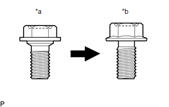
*a |
Centering Bolt |
|
*b |
Standard Bolt |
HINT:
- Centering bolts are used to install the door hinges to the door. The door cannot be adjusted with the centering bolts installed. Substitute the centering bolts with standard bolts (with washers) when making adjustments.
- The specified torque for standard bolts is shown in the standard bolt
chart.
Click here
.gif)
PROCEDURE
1. INSPECT BACK DOOR
(a) Check that the clearance measurements of areas "A" to "O" are within the standard ranges.
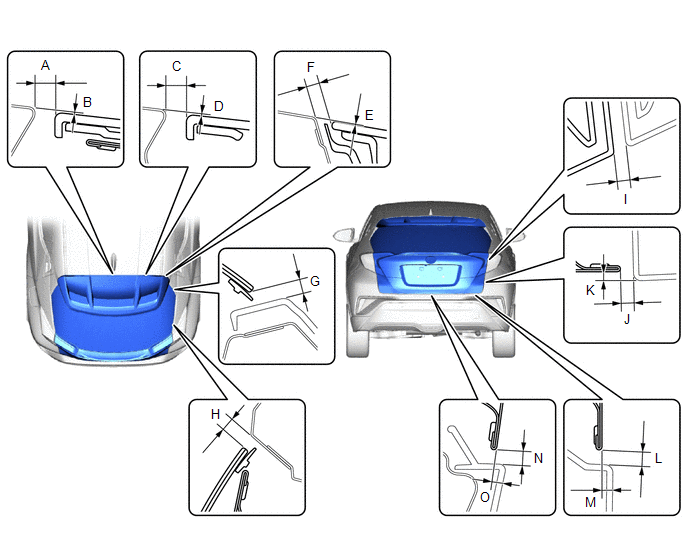 Standard Clearance
|
Area |
Measurement |
Area |
Measurement |
|---|---|---|---|
|
A |
7.1 to 11.1 mm (0.280 to 0.437 in.) |
B |
-1.0 to 3.0 mm (-0.039 to 0.118 in.) |
|
C |
7.1 to 11.1 mm (0.280 to 0.437 in.) |
D |
-1.0 to 3.0 mm (-0.039 to 0.118 in.) |
|
E |
-2.0 to 2.0 mm (-0.079 to 0.079 in.) |
F |
4.0 to 8.0 mm (0.157 to 0.315 in.) |
|
G |
3.5 to 8.5 mm (0.138 to 0.335 in.) |
H |
3.5 to 8.5 mm (0.138 to 0.335 in.) |
|
I |
3.3 to 7.3 mm (0.130 to 0.287 in.) |
J |
3.5 to 7.5 mm (0.138 to 0.295 in.) |
|
K |
2.4 to 5.4 mm (0.094 to 0.213 in.) |
L |
4.0 to 8.0 mm (0.157 to 0.315 in.) |
|
M |
2.8 to 5.8 mm (0.110 to 0.228 in.) |
N |
4.0 to 8.0 mm (0.157 to 0.315 in.) |
|
O |
3.8 to 6.8 mm (0.150 to 0.268 in.) |
- |
- |
2. REMOVE DECK TRIM REAR COVER
Click here
3. ADJUST BACK DOOR
|
(a) Loosen the 4 hinge bolts on the back door and adjust the back door position. |
|
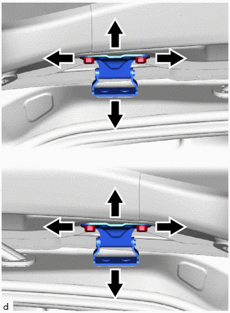
(b) Tighten the 4 hinge bolts on the back door after adjustment.
Torque:
19 N·m {194 kgf·cm, 14 ft·lbf}
|
(c) Using a T40 "TORX" socket wrench, slightly loosen the 2 striker mounting screws. |
|
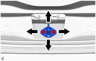
(d) Using a brass bar and a hammer, hit the striker to adjust its position.
(e) Using a T40 "TORX" socket wrench, tighten the 2 striker mounting screws after adjustment.
Torque:
23 N·m {235 kgf·cm, 17 ft·lbf}
4. INSTALL DECK TRIM REAR COVER
Click here
 Disassembly
DISASSEMBLY
PROCEDURE
1. REMOVE PACKAGE TRAY TRIM PANEL ASSEMBLY (w/ Package Tray Trim)
Click here
2. REMOVE TONNEAU COVER ASSEMBLY (w/ Tonneau Cover)
Click here
3. REMOVE BACK DOOR TRIM ...
 Reassembly
REASSEMBLY
PROCEDURE
1. INSTALL NO. 1 BACK DOOR EMBLEM
Click here
2. INSTALL NO. 2 BACK DOOR NAME PLATE
Click here
3. INSTALL NO. 1 BACK DOOR NAME PLATE (w/ Brand Mark)
Click here
...
Other materials:
Toyota CH-R Owners Manual > Before driving: Trailer towing
Toyota does not recommend towing a trailer with your vehicle.
Toyota also does not recommend the installation of a tow hitch or
the use of a tow hitch carrier for a wheelchair, scooter, bicycle, etc. Your vehicle
is not designed for trailer towing or for the use of tow hitch mounted carriers. ...
Toyota CH-R Service Manual > Audio And Visual System(for Radio And Display Type): Diagnostic Trouble Code Chart
DIAGNOSTIC TROUBLE CODE CHART
Audio and Visual System
DTC No.
Detection Item
Link
B1324
Lost Communication with Meter
B1551
HD Radio Tuner Malfunction
B ...
Toyota C-HR (AX20) 2023-2026 Owner's Manual
Toyota CH-R Owners Manual
- For safety and security
- Instrument cluster
- Operation of each component
- Driving
- Interior features
- Maintenance and care
- When trouble arises
- Vehicle specifications
- For owners
Toyota CH-R Service Manual
- Introduction
- Maintenance
- Audio / Video
- Cellular Communication
- Navigation / Multi Info Display
- Park Assist / Monitoring
- Brake (front)
- Brake (rear)
- Brake Control / Dynamic Control Systems
- Brake System (other)
- Parking Brake
- Axle And Differential
- Drive Shaft / Propeller Shaft
- K114 Cvt
- 3zr-fae Battery / Charging
- Networking
- Power Distribution
- Power Assist Systems
- Steering Column
- Steering Gear / Linkage
- Alignment / Handling Diagnosis
- Front Suspension
- Rear Suspension
- Tire / Wheel
- Tire Pressure Monitoring
- Door / Hatch
- Exterior Panels / Trim
- Horn
- Lighting (ext)
- Mirror (ext)
- Window / Glass
- Wiper / Washer
- Door Lock
- Heating / Air Conditioning
- Interior Panels / Trim
- Lighting (int)
- Meter / Gauge / Display
- Mirror (int)
- Power Outlets (int)
- Pre-collision
- Seat
- Seat Belt
- Supplemental Restraint Systems
- Theft Deterrent / Keyless Entry

0.0096