Toyota CH-R Service Manual: Disassembly
DISASSEMBLY
PROCEDURE
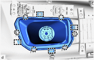
1. REMOVE SHIFTING HOLE COVER SUB-ASSEMBLY
|
(a) Disengage the 4 guides and 6 claws to remove the shifting hole cover sub-assembly from the upper console panel sub-assembly. |
|
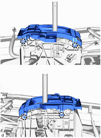
2. REMOVE SHIFT POSITION INDICATOR
|
(a) Remove the 3 screws and shift position indicator from the upper console panel sub-assembly. |
|
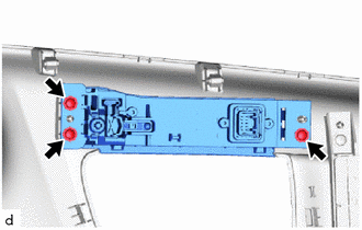
3. REMOVE SHIFT LEVER HOUSING BRACKET SUB-ASSEMBLY
|
(a) Disengage the 4 claws to remove the shift lever housing bracket sub-assembly from the shift lock control unit assembly. |
|
 Removal
REMOVAL
PROCEDURE
1. SECURE VEHICLE
(a) Fully apply the parking brake and chock a wheel.
CAUTION:
Make sure to apply the parking brake and chock a wheel before
p ...
 Inspection
INSPECTION
PROCEDURE
1. INSPECT SHIFT LOCK CONTROL UNIT ASSEMBLY (w/o Smart Key System)
HINT:
If the results of the following inspections are as specified but a malfunction
has occurred, replace ...
Other materials:
Toyota CH-R Service Manual > Meter / Gauge System: Washer Fluid Level Warning Switch Circuit
DESCRIPTION
The combination meter assembly and level warning switch assembly are connected
via direct line. The combination meter assembly determines the washer fluid level
and outputs warning messages according to the washer fluid level warning switch
ON/OFF signal.
WIRING DIAGRAM
CAUTIO ...
Toyota CH-R Service Manual > Glove Box Light: Inspection
INSPECTION
PROCEDURE
1. INSPECT GLOVE BOX LIGHT ASSEMBLY
(a) Check that the LED illuminates.
(1) Apply battery voltage to the glove box light assembly and check that
the LED illuminates.
OK:
Measurement Condition
Specified Condition
...
Toyota C-HR (AX20) 2023-2026 Owner's Manual
Toyota CH-R Owners Manual
- For safety and security
- Instrument cluster
- Operation of each component
- Driving
- Interior features
- Maintenance and care
- When trouble arises
- Vehicle specifications
- For owners
Toyota CH-R Service Manual
- Introduction
- Maintenance
- Audio / Video
- Cellular Communication
- Navigation / Multi Info Display
- Park Assist / Monitoring
- Brake (front)
- Brake (rear)
- Brake Control / Dynamic Control Systems
- Brake System (other)
- Parking Brake
- Axle And Differential
- Drive Shaft / Propeller Shaft
- K114 Cvt
- 3zr-fae Battery / Charging
- Networking
- Power Distribution
- Power Assist Systems
- Steering Column
- Steering Gear / Linkage
- Alignment / Handling Diagnosis
- Front Suspension
- Rear Suspension
- Tire / Wheel
- Tire Pressure Monitoring
- Door / Hatch
- Exterior Panels / Trim
- Horn
- Lighting (ext)
- Mirror (ext)
- Window / Glass
- Wiper / Washer
- Door Lock
- Heating / Air Conditioning
- Interior Panels / Trim
- Lighting (int)
- Meter / Gauge / Display
- Mirror (int)
- Power Outlets (int)
- Pre-collision
- Seat
- Seat Belt
- Supplemental Restraint Systems
- Theft Deterrent / Keyless Entry

0.009