
Toyota CH-R Service Manual: Removal
REMOVAL
PROCEDURE
1. SECURE VEHICLE
|
(a) Fully apply the parking brake and chock a wheel. CAUTION:
|
|
.png)
2. REMOVE SHIFT LEVER CAP
|
(a) Using a screwdriver with its tip wrapped in protective tape, disengage the 2 claws to remove the shift lever cap from the shift position indicator. NOTICE: Be careful not to damage the shift lever cap and instrument panel ornament. |
|
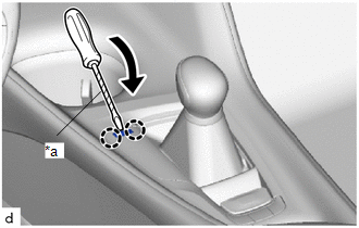
(b) Move the shift lever to N.
3. REMOVE SHIFT LEVER KNOB SUB-ASSEMBLY
Click here
.gif)
4. REMOVE REAR CONSOLE BOX ASSEMBLY
Click here
5. REMOVE NO. 1 CONSOLE BOX MOUNTING BRACKET
|
(a) Disengage the 3 clamps to separate the wire harness from the No. 1 console box mounting bracket. |
|
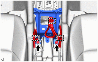
(b) Remove the 2 bolts and No. 1 console box mounting bracket from the vehicle body.
6. DISCONNECT TRANSMISSION CONTROL CABLE ASSEMBLY
.png) |
Remove in this Direction |
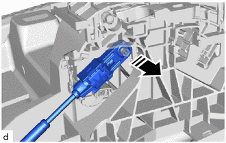
(a) Disconnect the end of the transmission control cable assembly from the floor shift shift lever assembly.
|
*1 |
Slider |
.png) |
Push |
|
|
Remove in this Direction |
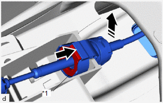
(b) Push in the slider and remove the transmission control cable from the floor shift shift lever assembly as shown in the illustration.
7. REMOVE FLOOR SHIFT SHIFT LEVER ASSEMBLY
|
(a) Disconnect the 2 connectors from the floor shift shift lever assembly. |
|
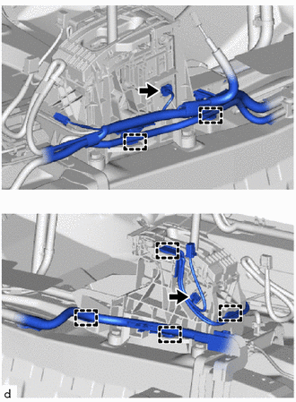
(b) Disengage the 6 clamps to separate the wire harness from the floor shift shift lever assembly.
|
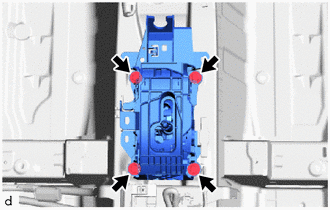
(c) Remove the 4 bolts and floor shift shift lever assembly from the vehicle body. |
|
 On-vehicle Inspection
ON-VEHICLE INSPECTION
PROCEDURE
1. SECURE VEHICLE
(a) Fully apply the parking brake and chock a wheel.
CAUTION:
Make sure to apply the parking brake and chock a wheel before performing
...
 Disassembly
DISASSEMBLY
PROCEDURE
1. REMOVE SHIFTING HOLE COVER SUB-ASSEMBLY
(a) Disengage the 4 guides and 6 claws to remove the shifting hole cover
sub-assembly from the upper console panel su ...
Other materials:
Toyota CH-R Service Manual > Maintenance: Rear Brake Flexible Hose
Components
COMPONENTS
ILLUSTRATION
*1
REAR FLEXIBLE HOSE
*2
GASKET
*3
UNION BOLT
-
-
Tightening torque for "Major areas involving basic vehicle performance
such as ...
Toyota CH-R Service Manual > Brake Booster: Reassembly
REASSEMBLY
PROCEDURE
1. INSTALL VACUUM WARNING SWITCH ASSEMBLY
(a) Install a new check valve grommet to the brake booster assembly.
(b) Install the vacuum sensor assembly to the brake booster assembly
as shown in the illustration.
...
Toyota C-HR (AX20) 2023-2026 Owner's Manual
Toyota CH-R Owners Manual
- For safety and security
- Instrument cluster
- Operation of each component
- Driving
- Interior features
- Maintenance and care
- When trouble arises
- Vehicle specifications
- For owners
Toyota CH-R Service Manual
- Introduction
- Maintenance
- Audio / Video
- Cellular Communication
- Navigation / Multi Info Display
- Park Assist / Monitoring
- Brake (front)
- Brake (rear)
- Brake Control / Dynamic Control Systems
- Brake System (other)
- Parking Brake
- Axle And Differential
- Drive Shaft / Propeller Shaft
- K114 Cvt
- 3zr-fae Battery / Charging
- Networking
- Power Distribution
- Power Assist Systems
- Steering Column
- Steering Gear / Linkage
- Alignment / Handling Diagnosis
- Front Suspension
- Rear Suspension
- Tire / Wheel
- Tire Pressure Monitoring
- Door / Hatch
- Exterior Panels / Trim
- Horn
- Lighting (ext)
- Mirror (ext)
- Window / Glass
- Wiper / Washer
- Door Lock
- Heating / Air Conditioning
- Interior Panels / Trim
- Lighting (int)
- Meter / Gauge / Display
- Mirror (int)
- Power Outlets (int)
- Pre-collision
- Seat
- Seat Belt
- Supplemental Restraint Systems
- Theft Deterrent / Keyless Entry

0.0091