Toyota CH-R Service Manual: Removal
REMOVAL
CAUTION / NOTICE / HINT
The necessary procedures (adjustment, calibration, initialization, or registration) that must be performed after parts are removed, installed, or replaced during the transmission revolution sensor removal/installation are shown below.
Necessary Procedure After Parts Removed/Installed/Replaced|
Replacement Part or Procedure |
Necessary Procedure |
Effect/Inoperative when not Performed |
Link |
|---|---|---|---|
|
Disconnect cable from negative battery terminal |
Initialize back door lock |
Power door lock control system |
|
|
Memorize steering angle neutral point |
Lane departure alert system (w/ Steering Control) |
|
|
|
Pre-collision system |
PROCEDURE
1. PRECAUTION
NOTICE:
After turning the ignition switch off, waiting time may be required before disconnecting the cable from the negative (-) battery terminal. Therefore, make sure to read the disconnecting the cable from the negative (-) battery terminal notice before proceeding with work.
Click here
.gif)
2. DISCONNECT CABLE FROM NEGATIVE BATTERY TERMINAL
Click here
NOTICE:
When disconnecting the cable, some systems need to be initialized after the cable is reconnected.
Click here
3. REMOVE BATTERY
Click here
4. REMOVE NO. 2 CYLINDER HEAD COVER
Click here
5. REMOVE RADIATOR COVER
Click here
6. REMOVE NO. 1 AIR CLEANER INLET
Click here
7. REMOVE AIR CLEANER CAP WITH AIR CLEANER HOSE
Click here
8. REMOVE AIR CLEANER CASE SUB-ASSEMBLY
Click here
9. REMOVE ECM
Click here
10. REMOVE BATTERY CLAMP SUB-ASSEMBLY
Click here
11. REMOVE TRANSMISSION REVOLUTION SENSOR (NIN)
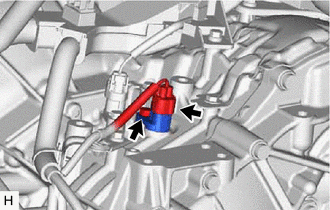
(a) Disconnect the connector.
(b) Remove the bolt and transmission revolution sensor (NIN) from the continuously variable transaxle assembly.
(c) Remove the O-ring from the transmission revolution sensor (NIN).
12. REMOVE TRANSMISSION REVOLUTION SENSOR (NOUT)
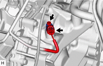
(a) Disconnect the connector.
(b) Remove the bolt and transmission revolution sensor (NOUT) from the continuously variable transaxle assembly.
(c) Remove the O-ring from the transmission revolution sensor (NOUT).
13. REMOVE TRANSMISSION REVOLUTION SENSOR (NT)
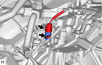
(a) Disconnect the connector.
(b) Remove the bolt and transmission revolution sensor (NT) from the continuously variable transaxle assembly.
(c) Remove the O-ring from the transmission revolution sensor (NT).
 Components
COMPONENTS
ILLUSTRATION
*1
AIR CLEANER CAP WITH AIR CLEANER HOSE
*2
AIR CLEANER CASE SUB-ASSEMBLY
*3
BATTERY CLAMP SUB-ASSEM ...
 Inspection
INSPECTION
PROCEDURE
1. INSPECT TRANSMISSION REVOLUTION SENSOR (NIN)
*a
Component without harness connected
(Transmission Revolution Sensor (NIN))
(a) Measure t ...
Other materials:
Toyota CH-R Service Manual > Airbag System: Short in Side Squib RH Circuit (B1820/55-B1823/55)
DESCRIPTION
The side squib RH circuit consists of the airbag sensor assembly and front seat
airbag assembly RH.
The airbag sensor assembly uses this circuit to deploy the airbag when deployment
conditions are met.
These DTCs are stored when a malfunction is detected in the side squib RH circu ...
Toyota CH-R Service Manual > Console Box Light: Inspection
INSPECTION
PROCEDURE
1. INSPECT INSTRUMENT CLUSTER FINISH PANEL GARNISH
(a) Check that the LED illuminates.
(1) Apply battery voltage to the instrument cluster finish panel garnish
and check that the LED illuminates.
OK:
Measurement Condition
...
Toyota C-HR (AX20) 2023-2026 Owner's Manual
Toyota CH-R Owners Manual
- For safety and security
- Instrument cluster
- Operation of each component
- Driving
- Interior features
- Maintenance and care
- When trouble arises
- Vehicle specifications
- For owners
Toyota CH-R Service Manual
- Introduction
- Maintenance
- Audio / Video
- Cellular Communication
- Navigation / Multi Info Display
- Park Assist / Monitoring
- Brake (front)
- Brake (rear)
- Brake Control / Dynamic Control Systems
- Brake System (other)
- Parking Brake
- Axle And Differential
- Drive Shaft / Propeller Shaft
- K114 Cvt
- 3zr-fae Battery / Charging
- Networking
- Power Distribution
- Power Assist Systems
- Steering Column
- Steering Gear / Linkage
- Alignment / Handling Diagnosis
- Front Suspension
- Rear Suspension
- Tire / Wheel
- Tire Pressure Monitoring
- Door / Hatch
- Exterior Panels / Trim
- Horn
- Lighting (ext)
- Mirror (ext)
- Window / Glass
- Wiper / Washer
- Door Lock
- Heating / Air Conditioning
- Interior Panels / Trim
- Lighting (int)
- Meter / Gauge / Display
- Mirror (int)
- Power Outlets (int)
- Pre-collision
- Seat
- Seat Belt
- Supplemental Restraint Systems
- Theft Deterrent / Keyless Entry

0.007