Toyota CH-R Service Manual: Inspection
INSPECTION
PROCEDURE
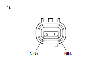
1. INSPECT TRANSMISSION REVOLUTION SENSOR (NIN)
|
*a |
Component without harness connected (Transmission Revolution Sensor (NIN)) |
(a) Measure the resistance according to the value(s) in the table below.
Standard Resistance:
|
Tester Connection |
Condition |
Specified Condition |
|---|---|---|
|
1 (NIN-) - 2 (NIN+) |
20°C (68°F) |
560 to 680 Ω |
If the result is not as specified, replace the transmission revolution sensor (NIN).
2. INSPECT TRANSMISSION REVOLUTION SENSOR (NOUT)
(a) Connect the battery to the transmission revolution sensor (NOUT) as shown in the illustration.
|
(b) Wave a magnetic object left and right in front of the tip of the transmission revolution sensor (NOUT) (5 mm (0.197 in.) gap or closer) to change the high/low signals while measuring the current. NOTICE: Be sure to wave a magnetic object during the inspection. The current will not change without waving the magnetic object as indicated by the arrow in the illustration. |
|
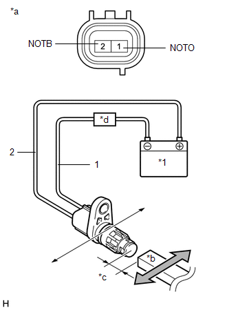
(c) Measure the current according to the value(s) in the table below.
Standard Current:
|
Tester Connection |
Condition |
Specified Condition |
|---|---|---|
|
1 (NOTO) - 2 (NOTB) |
Low Signal |
4 to 8 mA |
|
High Signal |
12 to 16 mA |
If the result is not as specified, replace the transmission revolution sensor (NOUT).
3. INSPECT TRANSMISSION REVOLUTION SENSOR (NT)
(a) Connect the battery to the transmission revolution sensor (NT) as shown in the illustration.
|
(b) Wave a magnetic object left and right in front of the tip of the transmission revolution sensor (NT) (5 mm (0.197 in.) gap or closer) to change the high/low signals while measuring the current. NOTICE: Be sure to wave a magnetic object during the inspection. The current will not change without waving the magnetic object as indicated by the arrow in the illustration. |
|
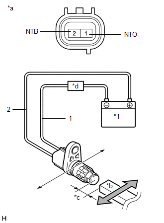
(c) Measure the current according to the value(s) in the table below.
Standard Current:
|
Tester Connection |
Condition |
Specified Condition |
|---|---|---|
|
1 (NTO) - 2 (NTB) |
Low Signal |
4 to 8 mA |
|
High Signal |
12 to 16 mA |
If the result is not as specified, replace the transmission revolution sensor (NT).
 Removal
REMOVAL
CAUTION / NOTICE / HINT
The necessary procedures (adjustment, calibration, initialization, or registration)
that must be performed after parts are removed, installed, or replaced during th ...
 Installation
INSTALLATION
PROCEDURE
1. INSTALL TRANSMISSION REVOLUTION SENSOR (NT)
(a) Apply Toyota Genuine CVT fluid FE to a new O-ring.
(b) Install the O-ring to the transmission revolution sensor (NT).
(c) ...
Other materials:
Toyota CH-R Service Manual > Center Airbag Sensor Assembly: Components
COMPONENTS
ILLUSTRATION
*A
w/ Rear Air Duct
-
-
*1
AIRBAG SENSOR ASSEMBLY
*2
REAR NO. 2 AIR DUCT
Tightening torque for "Major areas involving basic vehicle performance
...
Toyota CH-R Service Manual > Pre-collision System: How To Proceed With Troubleshooting
CAUTION / NOTICE / HINT
HINT:
Use these procedures to troubleshoot the pre-collision system.
*: Use the Techstream.
PROCEDURE
1.
VEHICLE BROUGHT TO WORKSHOP
NEXT
2.
...
Toyota C-HR (AX20) 2023-2026 Owner's Manual
Toyota CH-R Owners Manual
- For safety and security
- Instrument cluster
- Operation of each component
- Driving
- Interior features
- Maintenance and care
- When trouble arises
- Vehicle specifications
- For owners
Toyota CH-R Service Manual
- Introduction
- Maintenance
- Audio / Video
- Cellular Communication
- Navigation / Multi Info Display
- Park Assist / Monitoring
- Brake (front)
- Brake (rear)
- Brake Control / Dynamic Control Systems
- Brake System (other)
- Parking Brake
- Axle And Differential
- Drive Shaft / Propeller Shaft
- K114 Cvt
- 3zr-fae Battery / Charging
- Networking
- Power Distribution
- Power Assist Systems
- Steering Column
- Steering Gear / Linkage
- Alignment / Handling Diagnosis
- Front Suspension
- Rear Suspension
- Tire / Wheel
- Tire Pressure Monitoring
- Door / Hatch
- Exterior Panels / Trim
- Horn
- Lighting (ext)
- Mirror (ext)
- Window / Glass
- Wiper / Washer
- Door Lock
- Heating / Air Conditioning
- Interior Panels / Trim
- Lighting (int)
- Meter / Gauge / Display
- Mirror (int)
- Power Outlets (int)
- Pre-collision
- Seat
- Seat Belt
- Supplemental Restraint Systems
- Theft Deterrent / Keyless Entry

0.0068