Toyota CH-R Service Manual: Components
COMPONENTS
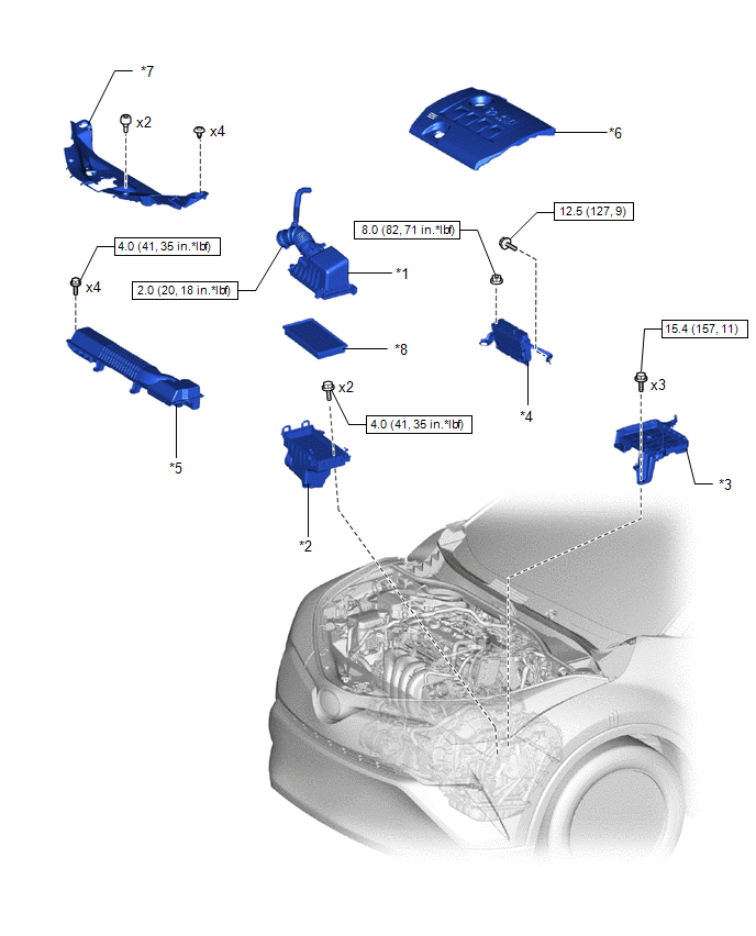
ILLUSTRATION
|
*1 |
AIR CLEANER CAP WITH AIR CLEANER HOSE |
*2 |
AIR CLEANER CASE SUB-ASSEMBLY |
|
*3 |
BATTERY CLAMP SUB-ASSEMBLY |
*4 |
ECM |
|
*5 |
NO. 1 AIR CLEANER INLET |
*6 |
NO. 2 CYLINDER HEAD COVER |
|
*7 |
RADIATOR COVER |
*8 |
AIR CLEANER FILTER ELEMENT SUB-ASSEMBLY |
.png) |
N*m (kgf*cm, ft.*lbf): Specified torque |
- |
- |
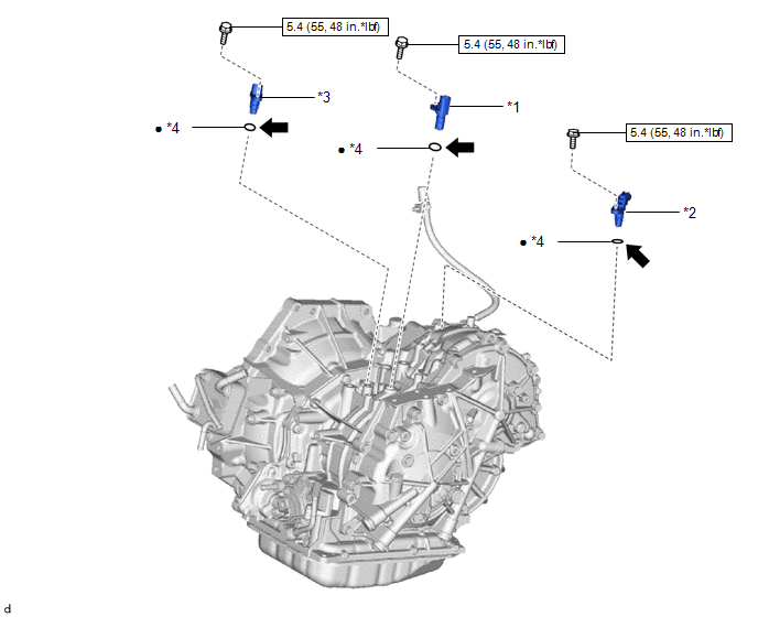
ILLUSTRATION
|
*1 |
TRANSMISSION REVOLUTION SENSOR (NIN) |
*2 |
TRANSMISSION REVOLUTION SENSOR (NOUT) |
|
*3 |
TRANSMISSION REVOLUTION SENSOR (NT) |
*4 |
O-RING |
|
|
N*m (kgf*cm, ft.*lbf): Specified torque |
● |
Non-reusable part |
.png) |
Toyota Genuine CVT Fluid FE |
- |
- |

 Removal
REMOVAL
CAUTION / NOTICE / HINT
The necessary procedures (adjustment, calibration, initialization, or registration)
that must be performed after parts are removed, installed, or replaced during th ...
Other materials:
Toyota CH-R Service Manual > Wireless Door Lock Control System(w/o Smart Key System): System Description
SYSTEM DESCRIPTION
WIRELESS DOOR LOCK CONTROL SYSTEM
The wireless door lock control system can be used to lock and unlock all doors
from a distance. The system is controlled by a door control transmitter assembly
which sends radio waves to the door control and tire pressure monitoring system
...
Toyota CH-R Service Manual > Airbag System: Lost communication with Side Airbag Sensor RH (B1622/81,B1623/81,B1632/81,B1633/81,B1642/81,B1643/81,B166D/81,B166E/81)
DESCRIPTION
The side collision sensor RH circuit (bus 1) consists of the airbag sensor assembly,
door side airbag sensor RH, No. 1 side airbag sensor RH and No. 2 side airbag sensor
RH.
The door side airbag sensor RH, No. 1 side airbag sensor RH and No. 2 side airbag
sensor RH detect impacts ...
Toyota C-HR (AX20) 2023-2026 Owner's Manual
Toyota CH-R Owners Manual
- For safety and security
- Instrument cluster
- Operation of each component
- Driving
- Interior features
- Maintenance and care
- When trouble arises
- Vehicle specifications
- For owners
Toyota CH-R Service Manual
- Introduction
- Maintenance
- Audio / Video
- Cellular Communication
- Navigation / Multi Info Display
- Park Assist / Monitoring
- Brake (front)
- Brake (rear)
- Brake Control / Dynamic Control Systems
- Brake System (other)
- Parking Brake
- Axle And Differential
- Drive Shaft / Propeller Shaft
- K114 Cvt
- 3zr-fae Battery / Charging
- Networking
- Power Distribution
- Power Assist Systems
- Steering Column
- Steering Gear / Linkage
- Alignment / Handling Diagnosis
- Front Suspension
- Rear Suspension
- Tire / Wheel
- Tire Pressure Monitoring
- Door / Hatch
- Exterior Panels / Trim
- Horn
- Lighting (ext)
- Mirror (ext)
- Window / Glass
- Wiper / Washer
- Door Lock
- Heating / Air Conditioning
- Interior Panels / Trim
- Lighting (int)
- Meter / Gauge / Display
- Mirror (int)
- Power Outlets (int)
- Pre-collision
- Seat
- Seat Belt
- Supplemental Restraint Systems
- Theft Deterrent / Keyless Entry

0.007