Toyota CH-R Service Manual: Transmission Control Switch Circuit
DESCRIPTION
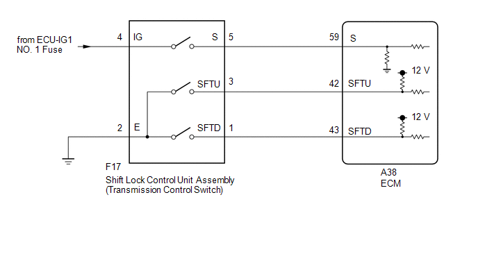
After moving the shift lever to M, it is possible to change the shift range between M1 and M7 using the transmission control switch. Moving the shift lever to "+" once raises the shift range by one, and moving the shift lever to "-" lowers the shift range by one.
WIRING DIAGRAM
CAUTION / NOTICE / HINT
NOTICE:
- Perform initialization when parts related to the continuously variable
transaxle are replaced.
Click here
.gif)
- Check that no DTCs are stored after performing initialization.
Click here
- Inspect the fuses for circuits related to this system before performing the following procedure.
PROCEDURE
|
1. |
CHECK DTC OUTPUT |
(a) Connect the Techstream to the DLC3.
(b) Turn the ignition switch to ON.
(c) Turn the Techstream on.
(d) Enter the following menus: Powertrain / Engine and ECT / Trouble Codes.
Powertrain > Engine and ECT > Trouble Codes(e) Read the DTCs using the Techstream.
|
Result |
Proceed to |
|---|---|
|
DTCs are not output |
A |
|
DTCs are output |
B |
| B | .gif) |
GO TO DTC CHART
|
|
.gif)
|
2. |
READ VALUE USING TECHSTREAM (SPORTS MODE SELECTION SW) |
(a) Connect the Techstream to the DLC3.
(b) Turn the ignition switch to ON.
(c) Turn the Techstream on.
(d) Enter the following menus: Powertrain / Engine and ECT / Data List.
Powertrain > Engine and ECT > Data List|
Tester Display |
|---|
|
Sports Mode Selection SW |
(e) In accordance with the display on the Techstream, read the Data List.
Powertrain > Engine and ECT > Data List|
Tester Display |
Measurement Item |
Range |
Normal Condition |
Diagnostic Note |
|---|---|---|---|---|
|
Sports Mode Selection SW |
Sport mode select switch status |
OFF or ON |
|
- |
|
Result |
Proceed to |
|---|---|
|
Data display is within Normal Condition range |
A |
|
Data display is not within Normal Condition range |
B |
| B | |
GO TO STEP 8 |
|
|
3. |
READ VALUE USING TECHSTREAM (SPORTS SHIFT UP SW AND SPORTS SHIFT DOWN SW) |
(a) Connect the Techstream to the DLC3.
(b) Turn the ignition switch to ON.
(c) Turn the Techstream on.
(d) Enter the following menus: Powertrain / Engine and ECT / Data List.
(e) In accordance with the display on the Techstream, read the Data List.
Powertrain > Engine and ECT > Data List|
Tester Display |
Measurement Item |
Range |
Normal Condition |
Diagnostic Note |
|---|---|---|---|---|
|
Sports Shift Up SW |
Sport shift up switch status |
OFF or ON |
|
- |
|
Sports Shift Down SW |
Sport shift down switch status |
OFF or ON |
|
- |
|
Tester Display |
|---|
|
Sports Shift Up SW |
|
Sports Shift Down SW |
|
Result |
Proceed to |
|---|---|
|
Data display is within Normal Condition range |
A |
|
Data display is not within Normal Condition range |
B |
| A | |
CHECK FOR INTERMITTENT PROBLEMS |
|
|
4. |
INSPECT SHIFT LOCK CONTROL UNIT ASSEMBLY (TRANSMISSION CONTROL SWITCH) |
|
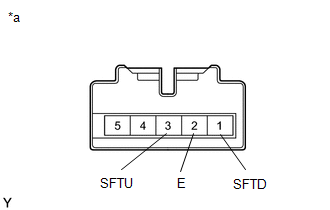
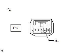
(a) Disconnect the F17 shift lock control unit assembly (transmission control switch) connector. |
|
(b) Measure the resistance according to the value(s) in the table below.
Standard Resistance:
|
Tester Connection |
Condition |
Specified Condition |
|---|---|---|
|
3 (SFTU) - 2 (E) |
Shift lever held in "+" |
Below 1 Ω |
|
3 (SFTU) - 2 (E) |
Shift lever in M |
10 kΩ or higher |
|
1 (SFTD) - 2 (E) |
Shift lever held in "-" |
Below 1 Ω |
|
1 (SFTD) - 2 (E) |
Shift lever in M |
10 kΩ or higher |
| NG | |
REPLACE SHIFT LOCK CONTROL UNIT ASSEMBLY (TRANSMISSION CONTROL SWITCH) |
|
|
5. |
CHECK HARNESS AND CONNECTOR (SHIFT LOCK CONTROL UNIT ASSEMBLY (TRANSMISSION CONTROL SWITCH) - BODY GROUND) |
|
(a) Disconnect the shift lock control unit assembly (transmission control switch) connector. |
|
(b) Measure the resistance according to the value(s) in the table below.
Standard Resistance:
|
Tester Connection |
Switch Condition |
Specified Condition |
|---|---|---|
|
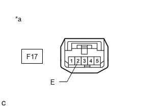
F17-2 (E) - Body ground |
Always |
Below 1 Ω |
| NG | |
REPAIR OR REPLACE HARNESS OR CONNECTOR (TRANSMISSION CONTROL SWITCH - ECM) |
|
|
6. |
CHECK HARNESS AND CONNECTOR (TRANSMISSION CONTROL SWITCH - ECM) |
|
(a) Disconnect the ECM connector. |
|
(b) Measure the resistance according to the value(s) in the table below.
Standard Resistance:
|
Tester Connection |
Condition |
Specified Condition |
|---|---|---|
|
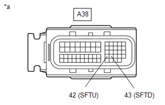
A38-43 (SFTD) - Body ground |
Shift lever held in "-" |
Below 1 Ω |
|
A38-43 (SFTD) - Body ground |
Shift lever in M |
10 kΩ or higher |
|
A38-42 (SFTU) - Body ground |
Shift lever held in "+" |
Below 1 Ω |
|
A38-42 (SFTU) - Body ground |
Shift lever in M |
10 kΩ or higher |
| NG | |
REPAIR OR REPLACE HARNESS OR CONNECTOR (TRANSMISSION CONTROL SWITCH - ECM) |
|
|
7. |
REPLACE ECM |
(a) Replace the ECM.
Click here
| NEXT | |
PERFORM INITIALIZATION
|
|
8. |
INSPECT SHIFT LOCK CONTROL UNIT ASSEMBLY (TRANSMISSION CONTROL SWITCH) |
|
(a) Disconnect the F17 shift lock control unit assembly (transmission control switch) connector. |
|
(b) Measure the resistance according to the value(s) in the table below.
Standard Resistance:
|
Tester Connection |
Condition |
Specified Condition |
|---|---|---|
|
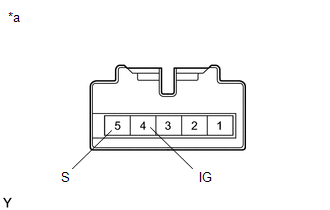
4 (IG) - 5 (S) |
Shift lever in M |
Below 1 Ω |
|
4 (IG) - 5 (S) |
Shift lever not in M |
10 kΩ or higher |
| NG | |
REPLACE SHIFT LOCK CONTROL UNIT ASSEMBLY (TRANSMISSION CONTROL SWITCH) |
|
|
9. |
CHECK HARNESS AND CONNECTOR (SHIFT LOCK CONTROL UNIT ASSEMBLY (TRANSMISSION CONTROL SWITCH) POWER SOURCE) |
|
(a) Disconnect the shift lock control unit assembly (transmission control switch) connector. |
|
(b) Measure the voltage according to the value(s) in the table below.
Standard Voltage:
|
Tester Connection |
Switch Condition |
Specified Condition |
|---|---|---|
|
F17-4 (IG) - Body ground |
Ignition switch ON |
11 to 14 V |
|
F17-4 (IG) - Body ground |
Ignition switch off |
Below 1 V |
| NG | |
CHECK POWER SOURCE CIRCUIT (TRANSMISSION CONTROL SWITCH) |
|
|
10. |
CHECK HARNESS AND CONNECTOR (TRANSMISSION CONTROL SWITCH - ECM) |
(a) Disconnect the F17 shift lock control unit assembly (transmission control switch) connector.
(b) Disconnect the A38 ECM connector.
(c) Measure the resistance according to the value(s) in the table below.
Standard Resistance:
|
Tester Connection |
Condition |
Specified Condition |
|---|---|---|
|
F17-5 (S) - A38-59 (S) |
Always |
Below 1 Ω |
|
F17-5 (S) - Body ground and other terminals |
Always |
10 kΩ or higher |
|
A38-59 (S) - Body ground and other terminals |
Always |
10 kΩ or higher |
| NG | |
REPAIR OR REPLACE HARNESS OR CONNECTOR (TRANSMISSION CONTROL SWITCH - ECM) |
|
|
11. |
REPLACE ECM |
(a) Replace the ECM.
Click here
| NEXT | |
PERFORM INITIALIZATION
|
 Output Speed Sensor Circuit No Signal (P0722,P077C,P077D)
DESCRIPTION
The ECM receives a signal from the transmission revolution sensor (NOUT) installed
in the continuously variable transaxle and determines the output shaft (secondary
pulley) speed in o ...

Other materials:
Toyota CH-R Service Manual > Air Conditioning System(for Automatic Air Conditioning System With Side-mounted
Air Conditioner Pressure Sensor): Customize Parameters
CUSTOMIZE PARAMETERS
CUSTOMIZE AIR CONDITIONING SYSTEM
(a) Customizing with the Techstream.
NOTICE:
When the customer requests a change in a function, first make sure that
the function can be customized.
Be sure to make a note of the current settings before customizing.
Wh ...
Toyota CH-R Service Manual > Stop Light Switch: Components
COMPONENTS
ILLUSTRATION
*1
COWL SIDE TRIM BOARD LH
*2
FRONT DOOR SCUFF PLATE LH
*3
NO. 1 AIR DUCT
*4
NO. 1 INSTRUMENT PANEL UNDER COVER SUB-ASSEMBLY
*5
STOP LIGHT SWITCH ASSE ...
Toyota C-HR (AX20) 2023-2026 Owner's Manual
Toyota CH-R Owners Manual
- For safety and security
- Instrument cluster
- Operation of each component
- Driving
- Interior features
- Maintenance and care
- When trouble arises
- Vehicle specifications
- For owners
Toyota CH-R Service Manual
- Introduction
- Maintenance
- Audio / Video
- Cellular Communication
- Navigation / Multi Info Display
- Park Assist / Monitoring
- Brake (front)
- Brake (rear)
- Brake Control / Dynamic Control Systems
- Brake System (other)
- Parking Brake
- Axle And Differential
- Drive Shaft / Propeller Shaft
- K114 Cvt
- 3zr-fae Battery / Charging
- Networking
- Power Distribution
- Power Assist Systems
- Steering Column
- Steering Gear / Linkage
- Alignment / Handling Diagnosis
- Front Suspension
- Rear Suspension
- Tire / Wheel
- Tire Pressure Monitoring
- Door / Hatch
- Exterior Panels / Trim
- Horn
- Lighting (ext)
- Mirror (ext)
- Window / Glass
- Wiper / Washer
- Door Lock
- Heating / Air Conditioning
- Interior Panels / Trim
- Lighting (int)
- Meter / Gauge / Display
- Mirror (int)
- Power Outlets (int)
- Pre-collision
- Seat
- Seat Belt
- Supplemental Restraint Systems
- Theft Deterrent / Keyless Entry

0.0093