Toyota CH-R Service Manual: Installation
INSTALLATION
CAUTION / NOTICE / HINT
CAUTION:
- Be sure to read Precaution thoroughly before servicing.
.png)
Click here
.gif)
- Wear protective gloves. Sharp areas on the parts may injure your hands.
HINT:
Lumbar support adjuster assembly is available only on the driver side.
PROCEDURE
1. INSTALL LUMBAR SUPPORT ADJUSTER ASSEMBLY
|
(a) Install the 2 front seatback edge protectors to the lumbar support adjuster assembly. |
|
.png)
(b) Engage the guides to install the lumbar support adjuster assembly to the front seatback frame sub-assembly as shown in the illustration.
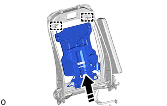
.png) |
Install in this Direction |
|
(c) Engage the claws to install the 2 front seatback edge protectors to the front seatback frame sub-assembly. |
|
.png)
|
(d) Engage the clamp. |
|
.png)
(e) Connect the connector.
2. INSTALL SEPARATE TYPE FRONT SEATBACK COVER WITH PAD
Click here
 Inspection
INSPECTION
PROCEDURE
1. INSPECT LUMBAR SUPPORT ADJUSTER ASSEMBLY
(a) Check the operation of the lumbar support adjuster assembly.
(1) Apply battery voltage to the lumbar motor connect ...
 Lumbar Switch
...
Other materials:
Toyota CH-R Service Manual > Front Door Window Frame Moulding: Installation
INSTALLATION
CAUTION / NOTICE / HINT
HINT:
Use the same procedure for the RH side and LH side.
The following procedure is for the LH side.
PROCEDURE
1. INSTALL FRONT DOOR FRONT WINDOW FRAME MOULDING
(a) Using an air riveter or hand riveter with a nose piece, install the front ...
Toyota CH-R Service Manual > Charging System: Lost Communication with Alternator (P161A)
DESCRIPTION
The ECM and generator assembly detect reception errors respectively.
The generator assembly reception error detected by the generator assembly is
sent to the ECM via LIN communication. If an error occurs in the ECM or generator
assembly, the ECM determines there is a LIN communicat ...
Toyota C-HR (AX20) 2023-2026 Owner's Manual
Toyota CH-R Owners Manual
- For safety and security
- Instrument cluster
- Operation of each component
- Driving
- Interior features
- Maintenance and care
- When trouble arises
- Vehicle specifications
- For owners
Toyota CH-R Service Manual
- Introduction
- Maintenance
- Audio / Video
- Cellular Communication
- Navigation / Multi Info Display
- Park Assist / Monitoring
- Brake (front)
- Brake (rear)
- Brake Control / Dynamic Control Systems
- Brake System (other)
- Parking Brake
- Axle And Differential
- Drive Shaft / Propeller Shaft
- K114 Cvt
- 3zr-fae Battery / Charging
- Networking
- Power Distribution
- Power Assist Systems
- Steering Column
- Steering Gear / Linkage
- Alignment / Handling Diagnosis
- Front Suspension
- Rear Suspension
- Tire / Wheel
- Tire Pressure Monitoring
- Door / Hatch
- Exterior Panels / Trim
- Horn
- Lighting (ext)
- Mirror (ext)
- Window / Glass
- Wiper / Washer
- Door Lock
- Heating / Air Conditioning
- Interior Panels / Trim
- Lighting (int)
- Meter / Gauge / Display
- Mirror (int)
- Power Outlets (int)
- Pre-collision
- Seat
- Seat Belt
- Supplemental Restraint Systems
- Theft Deterrent / Keyless Entry

0.0176