Toyota CH-R Service Manual: Output Speed Sensor Circuit No Signal (P0722,P077C,P077D)
DESCRIPTION
The ECM receives a signal from the transmission revolution sensor (NOUT) installed in the continuously variable transaxle and determines the output shaft (secondary pulley) speed in order to control the gear ratio.
The transmission revolution sensor (NOUT) detects the continuously variable transaxle output shaft (secondary pulley) speed and sends a signal to the ECM.
|
DTC No. |
Detection Item |
DTC Detection Condition |
Trouble Area |
MIL |
Memory |
|---|---|---|---|---|---|
|
P0722 |
Output Speed Sensor Circuit No Signal |
All of the following conditions are met (1 trip detection logic):
|
|
Comes on |
DTC stored |
|
P077C |
Output Speed Sensor Circuit Low |
There is no malfunction in transmission revolution sensor (NOUT) signals, and the transmission revolution sensor (NOUT) output voltage is less than 0.2 V for 2 seconds (1 trip detection logic) |
|
Comes on |
DTC stored |
|
P077D |
Output Speed Sensor Circuit High |
There is no malfunction in transmission revolution sensor (NOUT) signals, and the transmission revolution sensor (NOUT) output voltage is higher than 1.8 V for 2 seconds (1 trip detection logic). |
|
Comes on |
DTC stored |
MONITOR DESCRIPTION
The ECM receives a signal from the transmission revolution sensor (NOUT) installed in the continuously variable transaxle and determines the output shaft (secondary pulley) speed in order to control the gear ratio.
If the ECM detects no signal from the transmission revolution sensor (NOUT) even while the vehicle is moving, it will determine that the transmission revolution sensor (NOUT) is malfunctioning. The ECM will illuminate the MIL and store a DTC.
MONITOR STRATEGY
|
Related DTCs |
P0722: Output speed sensor (NOUT) / Verify pulse input P077C: Output speed sensor (NOUT) / Range check (Low voltage) P077D: Output speed sensor (NOUT) / Range check (High voltage) |
|
Required sensors/Components |
Transmission revolution sensor (NOUT) |
|
Frequency of operation |
Continuous |
|
Duration Conditions |
2 seconds |
|
MIL operation |
Immediately |
|
Sequence of operation |
None |
TYPICAL ENABLING CONDITIONS
All|
Battery voltage |
8 V or more |
|
Time after Battery voltage 8 V or more |
0.5 seconds or more |
|
Write Inhibit |
permit |
|
Time after Write status forbiddance to permit |
0.5 seconds or more |
|
Ignition switch |
ON |
|
Time after Ignition switch OFF to ON |
0.5 seconds or more |
|
Starter |
OFF |
|
Time after Starter ON to OFF |
0.5 seconds or more |
|
All of the following conditions are met: |
- |
|
Output shaft revolution |
300 rpm or more |
|
Output Speed Sensor Range check fail (P077C, P077D) (Pending / MIL) |
Not detected |
|
Turbine Speed Sensor revolution |
1050 rpm or more |
|
Transmission "R" range switch |
OFF |
|
Transmission Range Switch circuit fail (P0705) (Pending + MIL) |
Not detected |
|
Engine |
Running |
|
Park Neutral Position switch |
OFF |
|
One of the following conditions is met: |
- |
|
Command to Shift Solenoid |
OFF |
|
Command to Torque Converter Clutch Solenoid |
ON |
|
Shift Solenoid circuit fail (P099B, P099C) (Pending + MIL) |
Not detected |
|
Torque Converter Clutch Solenoid circuit fail (P2769, P2770) (Pending + MIL) |
Not detected |
|
Pressure Control Solenoid circuit fail (P2822, P282B) (Pending + MIL) |
Not detected |
|
Output Speed Sensor pulse input fail (P0722) (Pending + MIL) |
Not detected |
TYPICAL MALFUNCTION THRESHOLDS
P0722:|
Output Speed Sensor revolution |
Less than 300 rpm |
|
Output Speed Sensor voltage |
Less than 0.2 V |
|
Output Speed Sensor voltage |
Higher than 1.8 V |
COMPONENT OPERATING RANGE
P0722:|
Output Speed Sensor revolution |
300 rpm or more |
|
Output Speed Sensor voltage |
0.2 to 1.8 V |
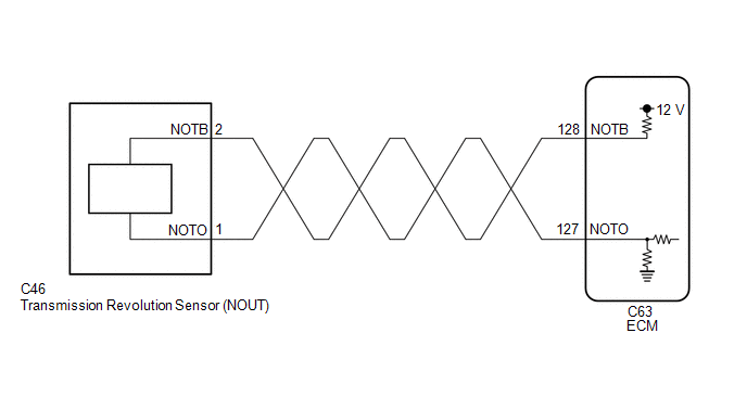
WIRING DIAGRAM
CAUTION / NOTICE / HINT
NOTICE:
- Perform initialization when parts related to the continuously variable
transaxle are replaced.
Click here
.gif)
- Check that no DTCs are stored after performing initialization.
Click here
- Perform the universal trip to clear permanent DTCs.
Click here
HINT:
After performing repair, clear the DTCs and perform the following procedure to check that DTCs are not output.
- Drive the vehicle for 2 seconds or more at 6 km/h (4 mph) or more with the shift lever in D.
- Check for DTCs again.
Click here
PROCEDURE
|
1. |
READ VALUE USING TECHSTREAM (SPD (NOUT) AND NOUT SENSOR VOLTAGE) |
(a) Connect the Techstream to the DLC3.
(b) Turn the ignition switch to ON.
(c) Turn the Techstream on.
(d) Enter the following menus: Powertrain / Engine and ECT / Data List.
Powertrain > Engine and ECT > Data List|
Tester Display |
|---|
|
SPD (NOUT) |
|
NOUT Sensor Voltage |
(e) In accordance with the display on the Techstream, read the Data List.
Powertrain > Engine and ECT > Data List|
Tester Display |
Measurement Item |
Range |
Normal Condition |
Diagnostic Note |
|---|---|---|---|---|
|
SPD (NOUT) |
Secondary pulley speed (NOUT) |
Min.: 0 rpm Max.: 12750 rpm |
|
Data is displayed in increments of 50 rpm. |
|
NOUT Sensor Voltage |
Secondary pulley speed (NOUT) sensor output voltage |
Min.: 0.000 V Max.: 4.999 V |
0.2 to 1.8 V: Engine idling (Vehicle stopped with shift lever in P or N) |
- |
- *1: w/ Canister Pump Module
- *2: w/o Canister Pump Module
|
Result |
Proceed to |
|---|---|
|
Data display is not within Normal Condition range |
A |
|
Data display is within Normal Condition range |
B |
| B | .gif) |
GO TO STEP 5 |
|
.gif)
|
2. |
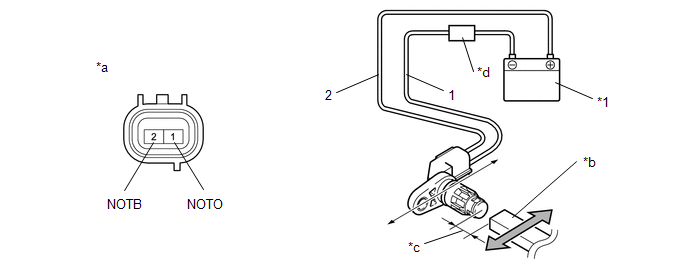
INSPECT TRANSMISSION REVOLUTION SENSOR (NOUT) |
(a) Remove the transmission revolution sensor (NOUT).
Click here
(b) Connect the battery to the sensor as shown in the illustration.
|
*1 |
Battery |
- |
- |
|
*a |
Component without harness connected (Transmission Revolution Sensor (NOUT)) |
*b |
Magnet |
|
*c |
5 mm or less |
*d |
Ammeter |
(c) Wave a magnetic object left and right in front of the transmission revolution sensor (NOUT) tip (5 mm (0.197 in.) or less) to change the high/low signals while measuring the current.
NOTICE:
Make sure to wave the magnetic object during the inspection. The current will not change without waving the magnetic object as indicated by the arrow in the illustration.
(d) Measure the current according to the value(s) in the table below.
Standard Current:
|
Tester Connection |
Condition |
Specified Condition |
|---|---|---|
|
1 (NOTO) - 2 (NOTB) |
Low signal |
4 to 8 mA |
|
1 (NOTO) - 2 (NOTB) |
High signal |
12 to 16 mA |
| NG | |
REPLACE TRANSMISSION REVOLUTION SENSOR (NOUT) |
|
|
3. |
CHECK HARNESS AND CONNECTOR (TRANSMISSION REVOLUTION SENSOR (NOUT) - ECM) |
(a) Disconnect the C46 transmission revolution sensor (NOUT) connector.
(b) Disconnect the C63 ECM connector.
(c) Measure the resistance according to the value(s) in the table below.
Standard Resistance:
|
Tester Connection |
Condition |
Specified Condition |
|---|---|---|
|
C46-1 (NOTO) - C63-127 (NOTO) |
Always |
Below 1 Ω |
|
C46-2 (NOTB) - C63-128 (NOTB) |
Always |
Below 1 Ω |
|
C46-1 (NOTO) or C63-127 (NOTO) - Body ground and other terminals |
Always |
10 kΩ or higher |
|
C46-2 (NOTB) or C63-128 (NOTB) - Body ground and other terminals |
Always |
10 kΩ or higher |
| NG | |
REPAIR OR REPLACE HARNESS OR CONNECTOR (TRANSMISSION REVOLUTION SENSOR (NOUT) - ECM) |
|
|
4. |
REPLACE ECM |
(a) Replace the ECM.
Click here
| NEXT | |
PERFORM INITIALIZATION |
|
5. |
REPLACE ECM |
(a) Replace the ECM.
Click here
| NEXT | |
PERFORM INITIALIZATION |
 Transmission Fluid Temperature Sensor "A" Circuit Low Input (P0712,P0713)
DESCRIPTION
The CVT fluid temperature sensor converts the fluid temperature into a resistance
value which is detected by the ECM.
The sensor resistance changes with the CVT fluid temperature. As t ...
 Transmission Control Switch Circuit
DESCRIPTION
After moving the shift lever to M, it is possible to change the shift range between
M1 and M7 using the transmission control switch. Moving the shift lever to "+" once
raise ...
Other materials:
Toyota CH-R Service Manual > Smart Key System(for Start Function): Vehicle Speed Signal Malfunction (B2282,B2283)
DESCRIPTION
DTC B2282 is stored when the vehicle speed signal sent by the combination meter
assembly via direct line and the vehicle speed signal sent via CAN communication
do not match.
DTC B2283 is stored when a malfunction in the vehicle speed sensor is detected.
DTC No.
...
Toyota CH-R Service Manual > Power Door Lock Control System: How To Proceed With Troubleshooting
CAUTION / NOTICE / HINT
HINT:
Use the following procedure to troubleshoot the power door lock control
system.
*: Use the Techstream.
PROCEDURE
1.
VEHICLE BROUGHT TO WORKSHOP
NEXT
...
Toyota C-HR (AX20) 2023-2026 Owner's Manual
Toyota CH-R Owners Manual
- For safety and security
- Instrument cluster
- Operation of each component
- Driving
- Interior features
- Maintenance and care
- When trouble arises
- Vehicle specifications
- For owners
Toyota CH-R Service Manual
- Introduction
- Maintenance
- Audio / Video
- Cellular Communication
- Navigation / Multi Info Display
- Park Assist / Monitoring
- Brake (front)
- Brake (rear)
- Brake Control / Dynamic Control Systems
- Brake System (other)
- Parking Brake
- Axle And Differential
- Drive Shaft / Propeller Shaft
- K114 Cvt
- 3zr-fae Battery / Charging
- Networking
- Power Distribution
- Power Assist Systems
- Steering Column
- Steering Gear / Linkage
- Alignment / Handling Diagnosis
- Front Suspension
- Rear Suspension
- Tire / Wheel
- Tire Pressure Monitoring
- Door / Hatch
- Exterior Panels / Trim
- Horn
- Lighting (ext)
- Mirror (ext)
- Window / Glass
- Wiper / Washer
- Door Lock
- Heating / Air Conditioning
- Interior Panels / Trim
- Lighting (int)
- Meter / Gauge / Display
- Mirror (int)
- Power Outlets (int)
- Pre-collision
- Seat
- Seat Belt
- Supplemental Restraint Systems
- Theft Deterrent / Keyless Entry

0.0071