Toyota CH-R Service Manual: Installation
INSTALLATION
PROCEDURE
1. INSTALL FLOOR SHIFT SHIFT LEVER ASSEMBLY
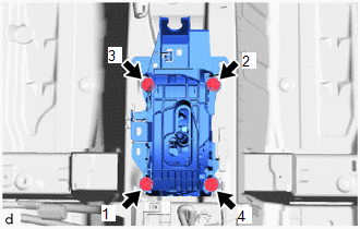
(a) Temporarily install the floor shift shift lever assembly to the body with the 4 bolts.
(b) Fully tighten the 4 bolts in the order shown in the illustration.
Torque:
12 N·m {122 kgf·cm, 9 ft·lbf}
(c) Engage the 6 clamps to install the wire harness to the floor shift shift lever assembly.
(d) Connect the 2 connectors to the floor shift shift lever assembly.
2. CONNECT TRANSMISSION CONTROL CABLE ASSEMBLY
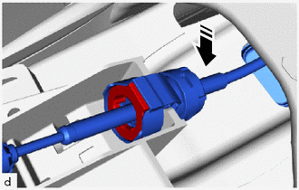
(a) Install the transmission control cable assembly to the floor shift shift lever assembly.
.png) |
Install in this Direction |
NOTICE:
Make sure that the transmission control cable assembly is securely locked.
|
|
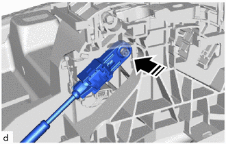
Install in this Direction |
(b) Connect the end of the transmission control cable assembly to the floor shift shift lever assembly.
NOTICE:
- Before connecting the transmission control cable assembly, check that the park/neutral position switch and shift lever are in N.
- Install the end of the transmission control cable assembly so that the lock piece faces the driver side.
- Install the end of the transmission control cable assembly all the way to the base of the pin.
3. INSTALL NO. 1 CONSOLE BOX MOUNTING BRACKET
.png)
(a) Install the No. 1 console box mounting bracket to the vehicle body with the 2 bolts.
(b) Engage the 3 clamps to install the wire harness to the No. 1 console box mounting bracket.
4. ADJUST SHIFT LEVER POSITION
Click here
.gif)
5. INSTALL CONSOLE BOX ASSEMBLY
Click here
6. INSTALL SHIFT LEVER KNOB SUB-ASSEMBLY
Click here
7. INSTALL SHIFT LEVER CAP
(a) Engage the 2 claws to install the shift lever cap to the instrument panel ornament.
8. INSPECT SHIFT LEVER POSITION
Click here
 Reassembly
REASSEMBLY
PROCEDURE
1. INSTALL SHIFT LEVER HOUSING BRACKET SUB-ASSEMBLY
(a) Engage the 4 claws to install the shift lever housing bracket sub-assembly
to the shift lock control unit ...
 Shift Lever Knob
Components
COMPONENTS
ILLUSTRATION
*1
SHIFT LEVER CAP
*2
SHIFT LEVER KNOB SUB-ASSEMBLY
Removal
REMOVAL
PROCEDURE
1. REMOVE SHIFT LEVER ...
Other materials:
Toyota CH-R Service Manual > Pre-collision System: Precaution
PRECAUTION
IGNITION SWITCH EXPRESSION
(a) The type of ignition switch used on this model differs depending on the specifications
of the vehicle. The expressions listed in the table below are used in this section.
Expression
Ignition Switch (Position)
Engine Swit ...
Toyota CH-R Service Manual > Wireless Door Lock Control System(w/o Smart Key System): Customize Parameters
CUSTOMIZE PARAMETERS
CUSTOMIZE WIRELESS DOOR LOCK CONTROL SYSTEM (w/o Entry and Start System)
HINT:
The following items can be customized.
NOTICE:
When the customer requests a change in a function, first make sure that
the function can be customized.
Be sure to make a note of th ...
Toyota C-HR (AX20) 2023-2026 Owner's Manual
Toyota CH-R Owners Manual
- For safety and security
- Instrument cluster
- Operation of each component
- Driving
- Interior features
- Maintenance and care
- When trouble arises
- Vehicle specifications
- For owners
Toyota CH-R Service Manual
- Introduction
- Maintenance
- Audio / Video
- Cellular Communication
- Navigation / Multi Info Display
- Park Assist / Monitoring
- Brake (front)
- Brake (rear)
- Brake Control / Dynamic Control Systems
- Brake System (other)
- Parking Brake
- Axle And Differential
- Drive Shaft / Propeller Shaft
- K114 Cvt
- 3zr-fae Battery / Charging
- Networking
- Power Distribution
- Power Assist Systems
- Steering Column
- Steering Gear / Linkage
- Alignment / Handling Diagnosis
- Front Suspension
- Rear Suspension
- Tire / Wheel
- Tire Pressure Monitoring
- Door / Hatch
- Exterior Panels / Trim
- Horn
- Lighting (ext)
- Mirror (ext)
- Window / Glass
- Wiper / Washer
- Door Lock
- Heating / Air Conditioning
- Interior Panels / Trim
- Lighting (int)
- Meter / Gauge / Display
- Mirror (int)
- Power Outlets (int)
- Pre-collision
- Seat
- Seat Belt
- Supplemental Restraint Systems
- Theft Deterrent / Keyless Entry

0.009